

Introduction: Automatic Desktop Fan


Being too warm sucks. What makes it suck even more? When you have to lean over to turn on your desk fan. Ain't nobody got energy for that!
This tutorial shows you how to make your desk fan turn on automatically when the temperature rises over a set threshold. Because we live in a world where such magic exists!
Step 1: Get the Parts


- A LightBlue Bean
- A fan (of any kind really)
- Three yellow buttons
- A power switch tail
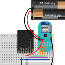
- A 2xAA battery holder with two AA batteries
- Some wire
The fan used is just a random fan from a hardware store but any type of fan can be used for the project. We will use a power switch tail to turn the fan on and off. A power switch tail lets you control power from your wall socket without having to mess around with any high voltages. Basically you connect the power switch tail to a pin on a microcontroller and turn the power on and off by setting the pin to high and low. Pretty neat!
To control the power switch tail, we'll use the LightBlue Bean since it has a built-in temperature sensor. We will also have three buttons to turn the fan on/off or to use it in auto mode where it turns on at a certain threshold.
Step 2: Drill Holes for the Button


We will mount the buttons and the LightBlue Bean on the foot of the fan. To fasten the buttons, use a whiteboard marker to put some color on the pins of the buttons and then press them against the foot of the fan to get small marks for drilling.
Remember to keep a bit of space between the buttons so that the other buttons don't get pushed down if you press one of them. And use a small drill so that the buttons almost sit by themselves in the holes. For the Bean, we need a hole that has room for 8 small wires: four from the buttons, two to a battery holder and two going to the power tail switch.
Step 3: Solder Wires to Buttons


On the bottom of the button (sounds like a indie movie title, doesn't it!), there's a small plus and a minus sign. Solder a piece of black wire to the leg with the minus sign next to it and a white one (or any other color of your fancy) to the one with the plus next to it. The wires need to be long enough to reach from the holes of the buttons to the hole to the Bean, and a bit further to give us some wiggle room when we solder them to the Bean.
Pull the wires through the holes we drilled for the buttons and glue the pins in the holes. Make sure to not use too much glue so that you can't press the buttons!
All the black wires from the buttons will go to GND on the Bean. Since we have a limited amount of GND pins on the Bean (two, to be exact) we'll connect the three black wires to each other so that we only need to solder one to the Bean.
Cut two of the wires and strip the ends so that you can wrap them around the base of the third of the black wires. Then solder them all together!
Step 4: Solder Button Wires to Bean
Next up we need to solder the wires from the buttons to the Bean. Pull the wires (three white and one black) through the hole we drilled for the Bean and solder the black one to GND and the white one to digital pins 3, 4 and 5.
Step 5: Connect Battery Holder

Take the battery holder and tape it to under the fan foot. Pull the two wires from the battery holder through the same hole as the button wires. Solder the red one to BAT on the Bean but leave the black one. We need to connect a wire from the power switch tail to the same GND pin so we'll wait until we have set those wires up.
Step 6: Connect Power Switch Tail

We need two wires to connect to the power switch tail: a red one going from +in on the power switch tail to pin 2 on the Bean and a white one going from -in to GND on the Bean.
Cut the wires to be as long as the power cord to the fan plus enough length to reach the pins on the power switch tail. Pull the wires through the back of the fan and up through the hole for the Bean. Solder the red one to digital pin 2 on the Bean. Put the other one through the remaining GND pin together with the black wire from the battery holder and solder them both there.
Connect the other ends to the pins on the power switch tail: the red one to +in and the white one to -in. We taped the wires to the fan's power cord to keep them in place but there are probably more elegant ways of solving the problem... Plug the power switch tail to a wall socket!
Step 7: Upload Code

We also printed out some labels for the buttons to keep track of which one's which. Recommended!
Connect to the LightBlue Bean in Bean Loader and upload this sketch to make sure that all the buttons are working alright. If you're not familiar with how to program the Bean, check out our getting started guide for OS X or guide for Windows.
#define BUTTON3 3
#define BUTTON4 4
#define BUTTON5 5

void setup() {
   pinMode(BUTTON3, INPUT_PULLUP);
   pinMode(BUTTON4, INPUT_PULLUP);
   pinMode(BUTTON5, INPUT_PULLUP);
   Serial.begin();
}

void loop() {
   if(!digitalRead(BUTTON3)){
     Serial.println("Button 1 has been pressed!");
   }

   else if(!digitalRead(BUTTON4)){
      Serial.println("Button 2 has been pressed!");
   }

   else if(!digitalRead(BUTTON5)){
      Serial.println("Button 3 has been pressed!");
   }

   Bean.sleep(300);
}
Right click on the Bean and choose "Use for virtual serial" and open the serial monitor in your Arduino IDE. It should say "Button X pressed!" in the serial monitor when you press the buttons.
If the buttons seem to be wired correctly, let's upload the full sketch!
/*

Sketch for automatic fan using the LightBlue Bean
Get the full tutorial at Hackster.io.

*/

#define BUTTON_ON 3
#define BUTTON_OFF 5
#define BUTTON_AUTO 4
#define POWER_SWITCH_PIN 2

bool autoMode = true;
bool fanIsOn = false;
int tempThreshold = 25;

void setup() {
   pinMode(BUTTON_ON, INPUT_PULLUP);
   pinMode(BUTTON_OFF, INPUT_PULLUP);
   pinMode(BUTTON_AUTO, INPUT_PULLUP);
   pinMode(POWER_SWITCH_PIN, OUTPUT);
   Serial.begin();
}

void loop() {
   // If the ON button is pressed and fan is turned off
   if(!digitalRead(BUTTON_ON) && !fanIsOn){
      digitalWrite(POWER_SWITCH_PIN, HIGH);
      Bean.setLed(255,0,0);
      delay(100);
      Bean.setLed(0,0,0);
      fanIsOn = true;
      autoMode = false;
   }

   // If the OFF button is pressed and the fan is turned on
   else if(!digitalRead(BUTTON_OFF) && fanIsOn){
      // Turn off the fan
      digitalWrite(POWER_SWITCH_PIN, LOW);
      Bean.setLed(255,0,0);
      delay(100);
      Bean.setLed(0,0,0);
      fanIsOn = false;
      autoMode = false;
   }

   // If the auto button is pressed
   else if(!digitalRead(BUTTON_AUTO)){
      Bean.setLed(255,0,0);
      delay(100);
      Bean.setLed(0,0,0);
      autoMode = true;
   }

   if(autoMode){
      // If the temperature is over the threshold but the fan is off
      if(Bean.getTemperature() > tempThreshold && !fanIsOn){
         // Turn on the fan
         digitalWrite(POWER_SWITCH_PIN, HIGH);
         fanIsOn = true;
         // Leave it on for 30 seconds
         delay(30000);
      }

      // If the temperature is under the threshold and the fan is on
      else if(Bean.getTemperature() <= tempThreshold && fanIsOn){
         // Turn off the fan
         digitalWrite(POWER_SWITCH_PIN, LOW);
         fanIsOn = false;
      }
   }
   Bean.sleep(500);
}
The fan should now turn on whenever the temperature is over 25°C, and stay on for at least 30 seconds or until you've cooled down to your normal self.


