

Introduction: Smartphone Controlled Mood Light


This tutorial teaches you how to make a mood light that you can change color and intensity of using your iPhone.
We will use the LightBlue Bean to control the lights. The LightBlue Bean is an Arduino compatible microcontroller with Bluetooth Low Energy, meaning that it's really easy to communicate with the Bean using your phone.
We will use the app LightBlue to control the light, so no iOS programming is required!
Step 1: Get the Parts
Material:
- A LightBlue Bean
- A 16 LED NeoPixel ring
- A 3.3V voltage regulator
- A 2.2 kΩ and a 10 kΩ resistor (both a part of this resistor kit)
- An NPN transistor
- A globe light shade
- Foamcore
- A USB cable
- Wires
Tools:
- Soldering iron
- Drilling machine
- Wire stripper
- Hot glue gun
- Knife
Step 2: Solder the Voltage Regulator
We will power the mood light with a 5V USB cable. The Bean runs on ~3V, so to step it down we will use a voltage regulator. Solder the voltage regulator onto the perfboard of the Bean to the holes below A1 and facing down. Make sure that you put it in the holes below A1, not in A1 itself. Cut the legs sticking out with a pair of pliers.
Take a bit of black wire and solder it from the top pin of the voltage regulator to GND on the Bean. Take a bit of red wire and solder it from the middle pin of the voltage regulator to BAT on the Bean.
Flip the Bean over and solder bridges between the top pin of the voltage regulator and the black wire and the middle pin and the red wire.


Step 3: Solder the Transistor
The transistor will be used as an amplifier to step up the Bean's signal from 3.3V to 5V for the NeoPixels.
These are the pins of the transistor:

Solder the transistor with the emitter pin through pin 5 on the Bean, the base pin two holes down and the collector one hole down from the base pin. Cut the legs sticking out through the back.

Step 4: Solder the Resistors
Take the 2.2 kΩ resistor and solder it between the middle pin of the transistor and the middle pin of the voltage regulator.
Take the 10 kΩ resistor and solder it to the bottom pin of the transistor and the bottom pin of the voltage regulator, one hole away from the transistor.
Flip the Bean over and solder a bridge from the 2.2 kΩ to the middle pin of the transistor and the other leg to the middle pin of the voltage regulator. Solder a bridge between the 10 kΩ resistor and the bottom pin of the voltage regulator but leave the leg by the transistor.


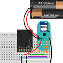
Step 5: Solder the NeoPixels
We will control the NeoPixels from pin 5 on the Bean. The signal will be amplified through the transistor and coming out through the collector pin. Solder a yellow wire from IN on the NeoPixels and to the collector pin on the transistor (the bottom one).
Take a piece of black wire and solder it to GND on the NeoPixels and GND on the Bean. Solder a red wire from VCC on the NeoPixels and to the hole under the to the bottom leg of the voltage regulator.

Flip the Bean over and solder a bridge from the bottom pin of the transistor to the yellow wire to the leg of the 10 kΩ resistor.
Solder a bridge from the red wire to the bottom leg of the voltage regulator.

Step 6: Drill Hole Through Light Globe

To pull the USB cable through the light globe we need to drill a hole through its neck.
Use a drill with the same diameter as the USB cable and slowly drill a hole through the neck of the light globe.
Step 7: Cut the USB Cable
Cut the end of the USB cable that doesn't go to the wall socket/computer. Strip about an inch of the wire and remove the foil. The USB cable we used is an USB 2.0 that is used to program Arduino UNOs. It has four wires in it: red, black, white and green.
We will only use the red and the black wire, so tape the rest to the side of the cable.


Use the wire stripper to strip the tips of the red and black wire. Put the USB cable it through the hole we drilled in the light globe's neck.

Solder the red wire next to the red wire from the NeoPixels and the black wire to the top leg of the voltage regulator.
Flip the Bean and solder bridges so that the red wire is connected to the bottom leg of the voltage regulator and the black wire is connected to the top leg.

Now the Neopixels will be provided with 5.0V from the USB cable and the Bean with the stepped-down 3.3V from the voltage regulator. The Bean is ready to go!

Step 8: Cut Bottom Plate
We will use foamcore to make a bottom plate for the lamp.
Put the light globe on the foamcore and press it down so that you get the outline of the neck.

Use the knife to cut out the inner circle. To avoid making the edge rugged, first cut the top layer of the foamcore, then the inner layer and last the bottom layer.

Use the hot glue gun to glue the Bean to the foamcore.

Place the bottom plate in the neck of the light globe and put glue along the edges of the plate.


Step 9: Upload Code

To set the color of the Neopixels, we will use the iOS app LightBlue. It has a demo screen where you can set the color of the Bean's on-board LED. What we will do is that we wake the Bean up whenever it is connected to and check the color of the on-board LED once a second. Whenever the color has changed, we will set the NeoPixels to the same color.
One of the awesome things about the LightBlue Bean is that it is programmed wirelessly, so we can upload code to it even when it's hot glued into a light globe.
Connect the USB to a power outlet or your computer. Upload this code to your Bean:
/*
  This sketch reads the values of the LightBlue Bean's onboard LED
  and sets a NeoPixel ring connected to pin 5 to the same color.


  This code is in the public domain.
*/


#include

// The pin that is connected to the NeoPixels
#define PIN 5


// The amount of LEDs in the NeoPixels
#define NUMPIXELS 16


// LedReading is the type we get when we call Bean.getLedValues();
// For example, to get the amount of red in the Bean's LED,
// we use ledColor.red to get a value from 0 to 255
LedReading ledColor;


// previousLedColor will be used to check if the LED's color has changed
LedReading previousLedColor;


// Set up the NeoPixel library
Adafruit_NeoPixel pixels = Adafruit_NeoPixel(NUMPIXELS, PIN, NEO_GRB + NEO_KHZ800);


void setup() {
  // Initialize the NeoPixels
  pixels.begin();


  // Program the Bean to wake up when connected
  Bean.enableWakeOnConnect(true);
}


void loop() {
  // Check if the Bean is connected to another device
  // to avoid the NeoPixels from turning off when it's disconnected
  if(Bean.getConnectionState()){
    // Get the values from the Bean's onboard LED
    ledColor = Bean.getLed();
    // Check if the color has changed
    if(ledColor.red != previousLedColor.red || ledColor.green != previousLedColor.green || ledColor.blue != previousLedColor.blue){
      //Set the NeoPixels to the same color as the Bean's LED
      for(int i=0;i<NUMPIXELS;i++){
        pixels.setPixelColor(i, pixels.Color(ledColor.red, ledColor.green, ledColor.blue));
        pixels.show();
      }
    // Update previousLedColor for the next loop
    previousLedColor = ledColor;
    }
  }
  else{
    // Sleep unless woken);
    Bean.sleep(0xFFFFFFF);
  }
}
Open the app LightBlue, connect to your Bean and change the LED color and intensity on the demo screen. You've just made yourself a smartphone controlled mood light!


