

Introduction: CAM Setup 1


Now that you've made your base level decisions about machining strategy, it's time to begin CAM. If you are an Autodesk employee, a student or educator, or a hobbyist or startup you qualify for the free version of Fusion 360! Follow these links to install the software.
Step 1: Opening the Spoon File in Fusion
1) Open Fusion 360.
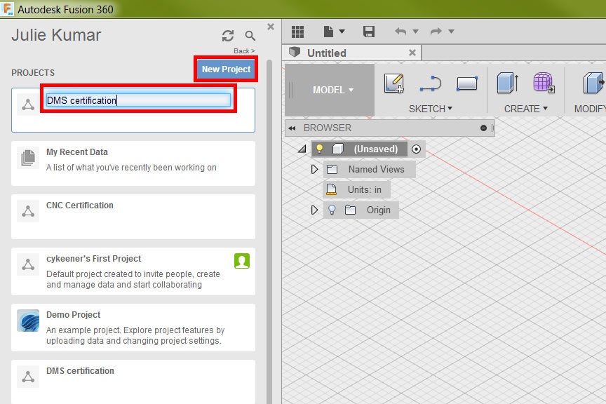
2) In the data panel on the left side, click New Project at the top. Name it "DMS certification part."
3) Download the DMS_spoon.ipt file, attached below.
4) In the data panel in Fusion, double click your new project, DMS certification part.

5) Click Upload near the top.
6) Click Select Files.
7) Select the DMS_spoon.ipt file, and click Open.
8) Click Upload.
9) Once the status bar is Complete, click Close.
10) Double click the part in the data panel to open the project.
11) Hide the data panel by pressing the icon with the nine small boxes.
It says "Hide Data Panel" when you hover your mouse over it.
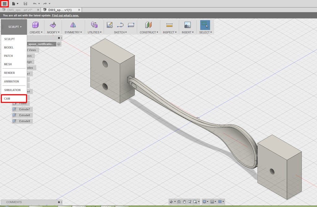
12) In the ribbon at the top left, change the Workspace to CAM.
13) Orbit the spoon until it is facing up, with the scoop of the spoon closer to you (see screenshot).
Do this with the view cube in the top right corner of the screen, by clicking the corner of the view cube where Front, Right, and Bottom intersect.
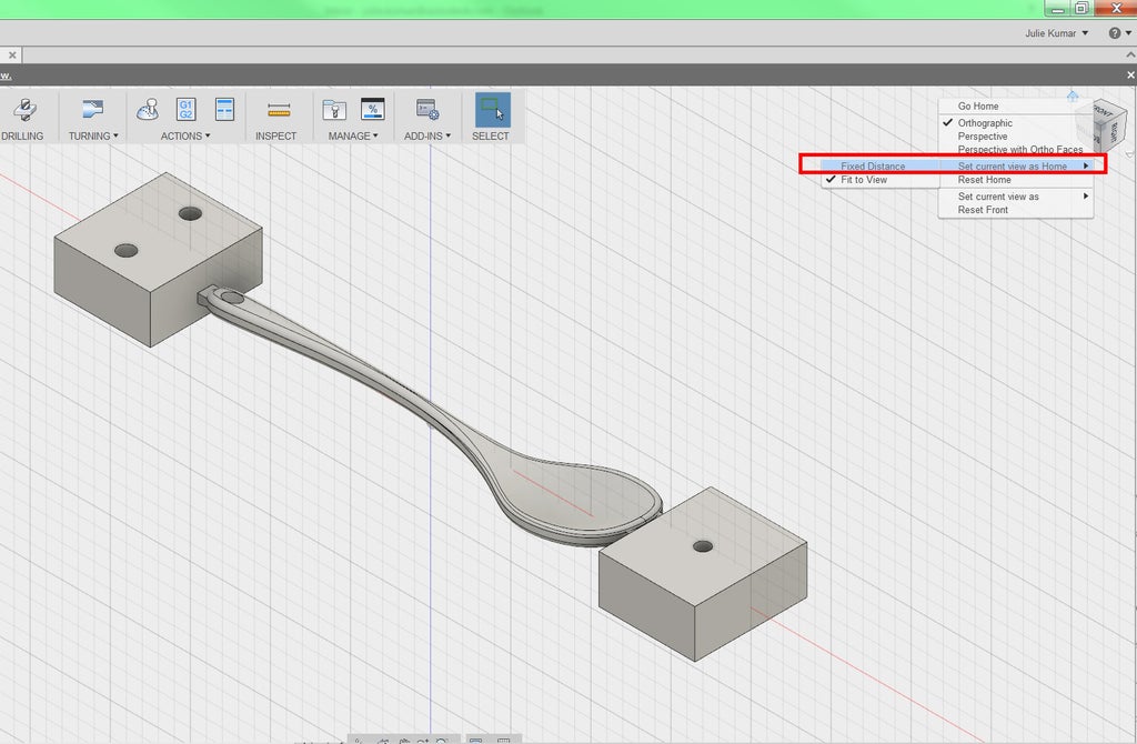
14) Hovering your mouse over the view cube, right click the icon of the Home and choose Set Current View as Home-Fixed Distance.
Now you can get back to this view anytime you click on the Home icon.
15) In the CAM feature tree on the left, check that your units are in inches.
If not, click the clipboard icon that appears next to the Units, change Unit Type to Inch, and click OK.
Attachments

Step 2: Install the Tool Library
At Pier 9, CNC staff maintains a tool library file to use when programming for the DMS. This library includes tool definitions and important information like diameter and flute length.You'll find it very useful for programming your parts, because all of these tools have the correct speeds and feeds for machining most materials on the DMS. To import the DMS tool library:
1) Follow the link to the Pier 9 CNC Tool Libraries Folder.
2) Download the latest .hsmlib file, following this naming convention:
P9_DMS_lib_date.hsmlib
4) Create a new folder on your hard drive called 'Pier 9 CNC Tool Libraries' and add this file.

5) On the right side of the CAM ribbon, in the Manage Section, click Tool Library.
This opens the tool library dialogue.
6) Right click the Local folder and click New Tool Library.
7) Type P9_DMS_date into the tool library name.
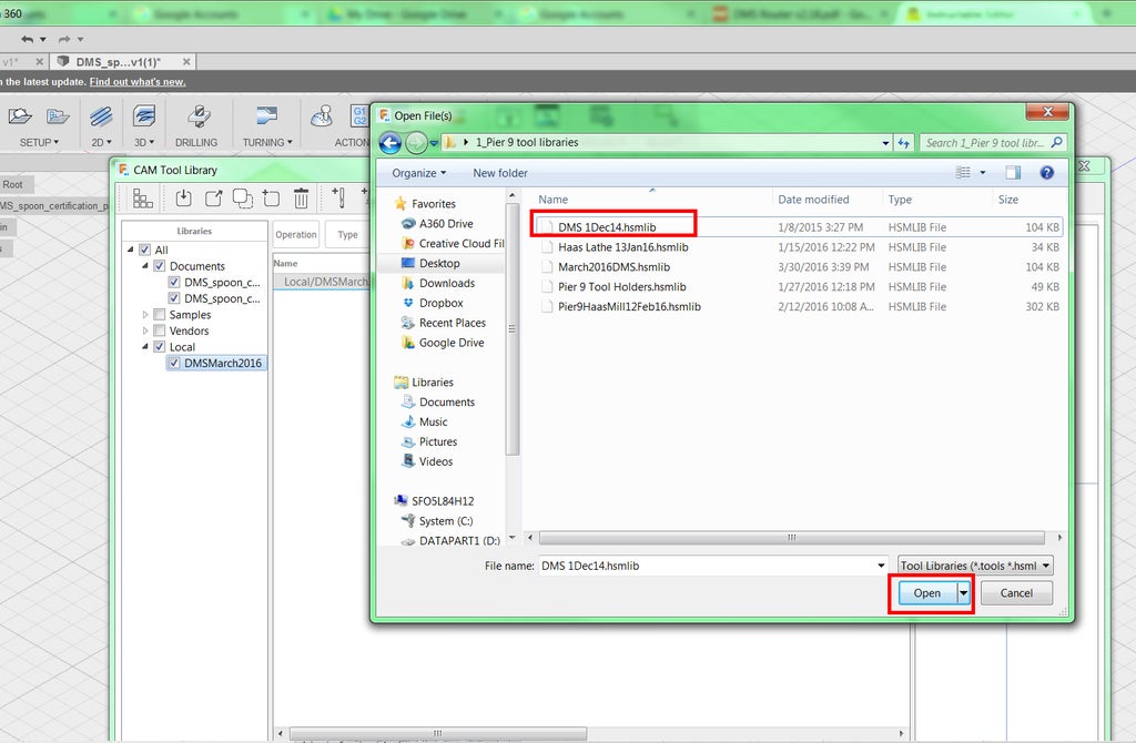
8) Right click P9_DMS_date and choose Import Tool Library.
9) Browse to the tool library you just saved on your hard drive and click Open.
You should see your new library populate with tools.
10) Click the arrow next to Samples to expand this folder. Make sure all the Sample libraries are unchecked, except the Inch-Aluminum library.
11) Exit this window by clicking the X in the upper right corner.

You just installed the Pier 9 DMS library!
Step 3: Setup 1
There are three steps in the CAM process: Setup, Toolpath, & Simulate.
Setup determines the location of the Work Coordinate System (WCS), the size of your raw material (stock), and the location of the part within the stock. For the spoon, you will need two setups, one before the flip and one after.

1) On the ribbon, click Setup.
The Setup Dialogue appears on the screen. It's organized into three tabs: Setup, Stock, and Post Process. This is how you will set the parameters of the setup.
In the Setup Dialogue, notice that Box Point appears in blue next to Stock Point. This means that you are being prompted to choose the location of the Work Coordinate System.
In the graphics window, the box surrounding the model, which represents the stock, contains many nodes. These nodes are potential locations for the WCS origin (Work Home).

2) In the graphics window, click the upper left node.
This moves the WCS to the upper left corner and defines its X, Y, and Z coordinates. Note that the x-axis points along the long axis of the part, the y-axis points away, and the z-axis points up, following the Right Hand Rule. This X, Y, and Z orientation is important, and you'll need to remember this when you place your stock in the DMS. For a more detailed explanation of the Work Coordinate System, watch this video: Setting up a Work Coordinate System.
3) In the Setup Dialogue, click the Stock tab.
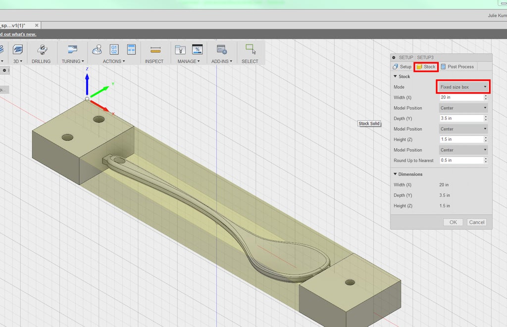
4) Change Stock Mode to Fixed size box.
Note that the default width (X), depth (Y), and height (Z) have been determined by the size of your model. These values--20" x 3.5" x 1.5"--are what you want.
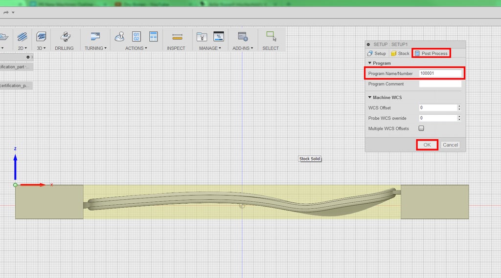
5) Click the Post Process tab. Change the program name/number to 100001.
This is the name of the program for post processing, which is the means by which your CAM program is converted into alphanumeric commands that the CNC machine will execute. This language is called G-code.
For the DMS post processor, your program name MUST be a six-digit number. Do not use programs that begin with number 9--we reserve those numbers for programs that are stored in the controller.
6) Click OK to generate the setup.
Setup 1 will appear in the Browser Tree on the left. You can always make changes to your setups or toolpaths in the browser tree by right clicking and choosing Edit.


