

Introduction: CAM and Machine a Mesh Model in Fusion 360


In this Instructable, you'll learn how to set up a CAM file in Fusion 360 directly from a high resolution mesh, such as an .stl or .obj file from a 3D scan.
Creating toolpaths directly from meshes became available in April 2017. This update to Fusion 360 gives a basic overview of how it works. Scroll halfway down and look for the animation of a Parallel toolpath on a topographic model.
In this Instructable, I'll use the example of a 3D scan of a banana peel that I machined in Delrin (plastic) on a five-axis router at Pier 9.
Step 1: Mesh Workspace Preview

1. Open Fusion 360.
2. Open the dropdown next to your name in the top right corner and choose Preferences.
3. On the left side of the dialog, click Preview.
4. Place a check next to Mesh Workspace.
5. Click OK.
Step 2: Mesh Workspace


1. In the Model Workspace, go to the Create dropdown.
2. Choose Create Mesh.
You will enter the Mesh Workspace.
3. In the Create dropdown, choose Insert Mesh.
File sizes will vary; my mesh file size was 28,314 KB and I got good results.
4. Choose your file and click Open.
5. Position the mesh and click OK.
6. In the Mesh workspace, you can reduce the polygon count, change the scale, and make other changes in the Modify dropdown.
Make sure your model is watertight and the polygon count is no larger than it needs to be. If you do not get good results within the Fusion mesh workspace, you can also use programs like MeshMixer or NetFabb.
Step 3: Model Workspace


In the Model Workspace, notice that the new MeshBody appears in the Browser Tree on the left (within Bodies).
Model any additional bodies you may need, including the part of the stock that will be held by the fixture. For my banana peel scan, I modeled the base of the banana peel, the section that would fit inside the vise jaws. I also modeled the stock and set its opacity to 30%.
Insert any additional components you need, including models of the fixture. I inserted a model of the Lang workholding vise, and created a fixed joint between the workholding model and the banana model (MeshBody and modelBase).
Step 4: CAM Workspace: Setup


1. Enter the CAM Workspace.
2. Create a new Setup.
3. Set your Work Coordinate System location.
I chose the center top of the vise receiver plate.
4. Under Model, choose your model body.
This is usually a combination of the MeshBody and an additional body that you modeled to hold the part inside the fixture.
If your display settings are set to Shaded with Visible Edges Only, your mesh will appear black due to the high polygon count. I suggest switching the Visual Style to Shaded.
5. Under Fixture, choose your fixture, if you have one.
Step 5: CAM Workspace: Setup, Stock Tab

1. In the Setup dialog, click the Stock tab.
2. Switch Stock Mode to From Solid
Only do this if you modeled your stock. If you didn't, use Fixed Size Box or Relative Size Box.
3. Choose your stock body.
4. Click OK to create your Setup.
Step 6: CAM Workspace: Toolpaths


Now, create toolpaths just as you would any other CAM file.
High resolution models can take a long time to simulate, so it can be a good idea to keep the finishing toolpaths at a low resolution (larger stepovers) until the very end.
You may find that it's useful to build all your toolpaths around a low resolution model of your part. At the end, switch the Setup Model Body to the high resolution model, regenerate your toolpaths, and re-run the simulation to check for collisions.
Step 7: Final Part


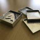
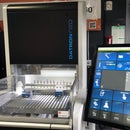
Here is the part being machined on the DMS five axis router at Pier 9.
Delrin is very machinable material--notice the high level of detail on the inside of the peel.
Happy mesh machining in Fusion 360!


