

Introduction: CNC Machining: Preparing Stock


Now that you have the G-code for the spoon on your USB drive, it's time to machine! In the next few lessons, you'll learn how to prepare and install your stock, insert and measure tools, establish a WCS (Work Coordinate System), and load and run programs on the DMS router.
Many of the following lessons have specifics that only apply to Pier 9's DMS router. If you are using a different router, use these lessons as guide posts. The broader steps -stock preparation, workholding, measuring tools, setting establish your work coordinate system - will be the same.
Step 1: Milling, Cutting, and Measuring Stock Material
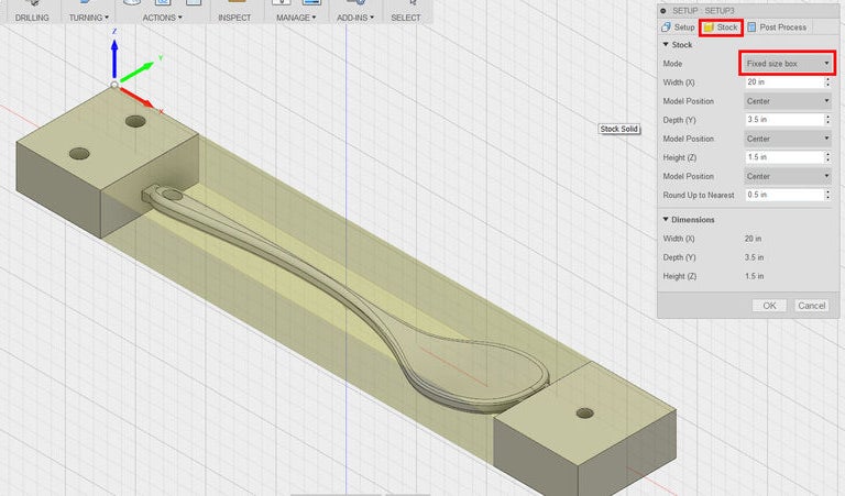
1) In Setup 1, recall that you chose a Fixed Size Box of 20" x 3.5" x 1.5". You will cut your stock to this size.

2) If you're starting with raw hardwood--in these pictures, you'll see poplar--use a joiner and planar to get the edges square and the piece milled to a thickness (height) of 1.5".

3) On the table saw, cut your piece 3.5" wide.
4) Finally, move to the compound miter saw (chop saw) to cut your piece to a length of 20".
If you have enough material, cut two pieces. It never hurts to have extra stock.
5) Use calipers to measure your actual stock size.
6) Update Setup 1 and Setup 2 in your CAM program with actual dimensions. Don't change any other parameters.
7) Right click each Setup and choose Generate Toolpaths with the new stock dimensions.
8) Revisit the Post Processing section to generate setup sheets and post process G-code to your USB drive.
Step 2: Adding Through Holes


2) Draw a line exactly 0.75" from the two edges of the stock (along the 20" length).
You will use this line to determine where your screws will go into the material. Use the Inspect tool (hot key i) in Fusion 360 to confirm that the holes in both sides of the rectangular prisms on either side of your spoon are 1.25" from the outer edges. In this way you can ensure that the drill bit will be 0.5" from your screws, preventing a collision.
If you are running a program in which a tool will come close to one of your workholding screws, use a brass screw instead of a drywall screw.

3) Find four 2" drywall screws, or wood screws between 2" and 2.25".

4) Choose a drill bit that is slightly larger in diameter than the threads of the screw.
You will be drilling through-holes in your material, so that the drywall screws are only digging into the spoiler board below. This is the proper way to cinch two materials together.

5) Clamp your stock and drill four holes. Stagger the holes by drilling the top hole on the drawn line, and the bottom hole closer to the edge of the stock, as shown.
You are staggering the holes to ensure that, after you flip the stock, your drywall screws will go into new locations on the spoiler board. This will create a more rigid workholding system. Verify that the holes aren't too close to the edge of the material.
6) Make sure the screws can slip through these through-holes without aid of a drill or screwdriver.
Step 3: Installing Stock in the DMS

1) Choose a spoiler board with a thickness of at least 0.75".
At Pier 9, there are usually extra spoiler boards stored behind the DMS. You can also cut one to size in the wood shop. Remember the area of the DMS machine bed is 5' x 5', so ensure that your spoiler board is over 4.5' in one direction.

2) Select four C-clamps from the wood shop.

3) Align the front edge of the spoiler board with the slot or channel in the acrylic machine bed, and then clamp the spoiler board down.
You will need to crawl into the machine and reach down to get enough clamping force to do this properly. If the machine is on, activate the E-stop.

4) Draw a 20" line about 3-4" from the front edge of the spoiler board.
5) Align the front edge of your stock to that line, and then use an impact driver or drill to screw the stock down into place.
In Fusion 360, check Setup 1 to confirm that your stock is oriented correctly. You placed the Work Coordinate System (WCS) in the upper left corner of the stock, with X along the 20" length, Y along the 3.5" depth, and Z along the 1.5" height. Your stock is placed correctly in the machine.

6) Using calipers, double check that your spoiler board is over 0.75" in thickness.
If your spoiler board is too thin, your 1/2" drill bit will go into the acrylic bed. You programmed the drill to go a total of 0.5" below the stock bottom. Notice in the image that you can easily measure the thickness of a material by placing the caliper upside down, putting the bottom of the caliper on your bottom surface (acrylic), and then sliding the back jaw down until it rests on the part you're measuring (plywood spoiler board). This distance is the same as the distance between the jaws.
7) Set up your laptop and setup sheets nearby so you can periodically check your machining notes or CAM simulation as you machine.
If you're at Pier 9, the DMS tool library Lista is an excellent place to set up. Also keep the DMS QuickStart Guide handy.


