

Introduction: Charlieplexing With the Raspberry Pi


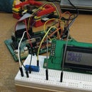

I've always been interested in Charlieplexing, but never had any means to get into it. When I got my Raspberry Pi, I figured it would make a great platform to learn how to Charlieplex.
There are already a ton of Instructables on Charlieplexing out there, so I won't go into the theory behind it, or how it works. This Instructable will instead focus on how I wired it up on my breadboard using 3 pairs of LEDs and 3 leads, then expanding it to 10 pairs of LEDs with 5 leads.
From a learning perspective, my objective was to learn about Charlieplexing. How does it work, and how do you code it.
Step 1: A Pair of LEDs


Charlieplexing is all about wiring up LEDs in pairs between sets of two leads. Each LED in the pair lights in a "different direction," if you will. This lets you run current from lead 1 to lead 2, and light one LED, then run current from lead 2 to lead 1 and light the other LED.
Wiring was going to be a mess, I figured, so I wanted my pairs of LEDs to be pretty compact. I put the LEDs in my breadboard facing opposite directions, in the same columns, practically touching, with a resister wired right next to them.
Step 2: Wiring Up the First Three Pairs


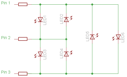
This image from wikipeida is a really good schematic of 3 pairs of LEDs Charlieplexed over 3 leads.
My wiring was very basic here, and I used short leads to keep it somewhat neat. I tried to label the picture with all the wires, but it was a bit too much, and didn't make things clear. So here's the wiring by color:
Orange: Lead 1 to Pair 1
Yellow: Pair 1 to Lead 2
Left Blue: Lead 1 to Pair 2
Straight Green: Pair 2 to Lead 3
Right Blue: Lead 2 to Pair 3
Wiggly Green: Pair 3 to Lead 3
Then I connected the Leads to the GPIO pins on my Raspberry Pi. I just chose to start at Pin 1 and work my way down, taking the first three GPIO pins. No other rhyme or reason for it. This instructable has a nice diagram of the order of the GPIO pins, and what each is used for.
Step 3: The Code and a Video
LEDS=[[1,2], [2,1], [1,3], [3,1], [2,3], [3,2]]
This works great, but is very static. To add a fourth lead, you need to go in and extend the list manually. This works well for a small number of leads, when you get to 10 leads, it's 90 LEDs. I wanted a way to automatically generate the list of LEDs. (See my comments in the final step for more on this.)
So, I created a list of leads, based on their GPIO pin number on the Raspberry Pi, then ran the leads through two for loops to generate the list automatically:
# define an array of pins used as leads
charliePins=[7,11,12]
# Define the array of LEDs. This is normally done
# by defining each pair separately, but I wanted the code
# to be easy to expand, so I went with this method of
# cycling through the pins and creating the pairs. It
# has the disadvantage of not making them in order for larger
# sets of pairs, but is easier to maintain, IMO.
charlieLEDS=[]
for i in range(0,len(charliePins)-1):
for j in range(i+1,len(charliePins)):
charlieLEDS.append([charliePins[i],charliePins[j]])
charlieLEDS.append([charliePins[j],charliePins[i]])
When I run the attached code, you get a pretty light display:
Attachments

Step 4: Overview
So far it's all been very simple--almost too simple. But Charlieplexing really is pretty simple once you get the hang of it. Let's take a minute, before we move on, to look back at where we've been.
We setup 3 pairs of LEDs, giving us a total of 6 LEDs.
We wired them up to three leads on the breadboard.
We connected the leads to the Raspberry Pi.
We wrote code to light the LEDs.
That's all there really is to do. You could modify the code to light the LEDs in a particular pattern if you wanted. My code does show three things to do--Light them one by one in order, light the top row, then the bottom row, and light them at random. Maybe you could have it do a wave, or a light chase or something like that. Pretty straight forward.
So what's left to do? Add more leads, and more LEDs, of course.
Step 5: Adding a Fourth Lead


Each time you add a lead, you add the same number of pairs of LEDs as the number of leads you already have.
WHAT?
Let's say you have three leads, and you want to add a fourth. You have three leads, so you add three pairs of LEDs. When you have four leads, and then add a fifth, you'll be able to add four more pairs of LEDs.
It works this way because each time you add a lead, you create a pair between the new lead, and each additional lead.
In other words, when I add Lead 4, I need to add a pair of LEDs between Lead 1 and Lead 4, between Lead 2 and Lead 4, and between Lead 3 and Lead 4.
The images below show the wiring process for adding these pairs of LEDs. One shows the process for Lead 1 to Pair 4 to Lead 4. The next shows Lead 2 to Pair 5 to Lead 4. And the last shows Lead 3 to Pair 6 to Lead 4.
Step 6: Adding the New LEDs to the Code
Three simple changes to the code allow for the addition of the new Lead.
1) Update the list holding the pins:
# define an array of pins used as leads
# NOTE: We've added the 4th lead to pin
# 13 on the RPi GPIO Header
charliePins=[7,11,12,4]
2) Update the top and bottom rows
# Define the top and bottom rows as the number of the
# LED in the list of LEDs to be created.
# NOTE: We've added three new pairs of LEDS
# to our top and bottom rows
top=[0,2,4,6,8,10]
bottom=[1,3,5,7,9,11]
3) Change the range for the random number flashing at the end
# Finally, flash them randomly
# NOTE: We've change the code to randomly flash
# The LEDs based on the number of LEDs automatically
for counter in range(0,26):
lightLED(charlieLEDS[randint(0,len(charlieLEDS)-1)
sleep(.1)
Attachments
Step 7: Adding a Fifth Lead


Adding a fourth lead seemed too simple, again. Add the lead, add the pairs of LEDs, and update the code. Let's do it again to show it's really just that simple.
The images in this step show how new pairs are added, and wired. Just remember, you'll add a pair for each lead you already have, then wire them from the existing leads to the new leads.
So you have four leads already. Add four pairs of LEDs. Then wire the first pair between the first lead and the new lead. Wire the second pair between the second lead and the new lead. And so on. The pictures below show this process.
Step 8: Adding the Code for the Fifth Lead

1) Add the fifth pin
# define an array of pins used as leads
# NOTE: We've added the 5th lead to pin
# 15 on the RPi GPIO Header
charliePins=[7,11,12,13,15]
2) Update the top and bottom row list
# Define the top and bottom rows as the number of the
# LED in the list of LEDs to be created.
# NOTE: We've added four new pairs of LEDS
# to our top and bottom rows
top=[0,2,4,6,8,10,12,14,16,18]
bottom=[1,3,5,7,9,11,13,15,17,19]
I didn't like the pins lighting out of order left to right, so I added two more optional snippets of code:
1) I created a new list of LEDs that would have them light in order:
# The order of the LEDs from left to right
# First the top pin, then the bottom pin
charlieOrder=[0,1,2,3,8,9,4,5,10,11,14,15,6,7,12,13,16,17,18,19]
2) I added code to run them in order:
# Next flash them in order from
# left to right
for led in charlieOrder:
lightLED(charlieLEDS[led])
sleep(0.25)
The final code is attached here, and again, very commented. And here's a video of the whole thing in action:
Attachments
Step 9: Followup Thoughts
I learned a few things while doing this project.
Charlieplexing is a lot less confusing than I thought it would be. I was convinced that it would be very difficult, but really, it's just about adding pairs of LEDs and hooking up the leads. The code required a little more work, but basically all you have to do to light a specific LED is put all the pins to input, then set the two pins for your specific LED to output, and put one HIGH and one LOW.
Adding new leads follows a nice little pattern. Add as many pairs of LEDs as you currently have leads, then wire each exiting lead to a pair, and each pair to the new lead.
I could have written some dynamic code to create the top and bottom lists. It's just counting from 0 to number of LEDs-1 by 2, and from 1 to the number of LEDS by 2. Then I wouldn't have to update it each time I add a new lead.
Keeping the LEDs in order--realizing which one in your LED list is the top LED on your 6th pair) is not difficult, but you might have a hard time writing the code to dynamically create the list in the "right" order for you. We've all seen LED cubes that are run with Charlieplexing. While you could dynamically build the list of LEDs as I did in my code, they would be entirely out of order, and you'd have to maintain a separate list to keep them in order anyway. I think this is why almost everyone just creates the list of LEDs manually as I said I didn't want to do in Step 3. There are usually, but not always, reasons everyone does something a certain way. :)
So where would I go from here? I'm not sure I have any real life applications. The LED cube thing has been done, and I've done some other LED projects with my Raspberry Pi (check out my youtube channel for them), so I don't really know what else I'd do with Charlieplexing.
Some things YOU might do include--POV wands: You could easily wire up 20 LEDs like I did, but do them in a row on a PCB connected to a stick to do the waving POV wand. LED Cubes: Yes, I just said they've been done, and I'm not going to do them, but that doesn't mean you can't! LED Matrix: You could easily setup a matrix of 90 LEDs in a 5x18 array, and create a scrolling message board (similar to the one I built). The possibilities are endless--well, almost endless. You only have so many GPIO pins on the Raspberry Pi.

Participated in the
LED Contest with Elemental LED

Participated in the
Hands-on Learning Contest

![Tim's Mechanical Spider Leg [LU9685-20CU]](https://content.instructables.com/FFB/5R4I/LVKZ6G6R/FFB5R4ILVKZ6G6R.png?auto=webp&crop=1.2%3A1&frame=1&width=306)


