

Introduction: Concrete Volume Control Knob W/ Arduino


An external volume control knob for your computer, I'm sure you've seen or at least heard of one. Spin the knob and your volume goes up or down and some can even mute with a click. I find listening to music productive while working but it can be a hassle to dump the volume when I have to take a call, multiple desktops, multiple keyboards, yada-yada.
So I have a (need/desire/want) to use one of these control knobs but not the (need/desire/want) to purchase one because what fun would that be. Buying a perfectly functional product seems wrong when you can spend weeks making something that works almost as good as a commercial version. Seriously, it's much more fun to design, tinker and mod a design of your own, especially when it actually works! I guess I'm a bit weird because I find most of the enjoyment in the design and building phases and the working part is sometimes anticlimactic as I've already seen it working in my head a thousand times.
In the end I did have a lot fun designing and building it, I learned more about doing it better the next time and I'm very happy to use it daily.
Supplies
Making the molds, base and button
- 3D Printer
- PLA
- Concrete / Mortar / Grout
Electronics
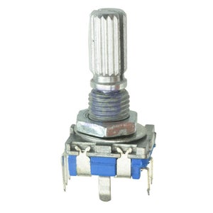
- Rotary Encoder
- Arduino Micro Pro (ATMega32u4) Clone
- Misc Wire
Tools
- Soldering Station
- Epoxy / Hot Glue Gun
- Sandpaper / Files
- Small Brush
Misc
- Paint / Primer
- Polyurethane
- Rubber Feet
Step 1: Concepualization


I had the idea and now I needed to turn a vague notion into something real. What to do first? I do what I always do, start doodling on some paper, draw out a few rough ideas and figure out how I could get from here to there. I also popped onto the Internet and took a look around to what others had done. I liked this, didn't like that, LOVED the other thing but maybe incorporate some of that into my next build, let's not get overly ambitions. Let's see if we can get some basic things working first.
The KNOB
First things first, I know I wanted a concrete knob as opposed to a 3D Printed knob (maybe a nice wooden knob?). I liked the concept of concrete, the heft, the look, it all worked for me. Whatever style it is (industrial?) I like it.
The BUTTON
I liked the idea of being able to push the puck and mute/un-mute the media player but I thought that the way most people balanced the knob, hovering on the rotary spindle, might wear it out so I moved to having the puck rest on the base and using a free moving center button to handle the "click" of the mute.
The BASE/BUTTON
I was lucky enough to purchase a 3D printer a while back and I use it every time I can and this time was no different. I figured I could design and print all the other base pieces. Easy to prototype and I could finish it up the way I wanted.
The ELECTRONICS
Using a rotary encoder with a click button was a no brainer and I already had a bag of them left over from some earlier project. However, there's a rub here. Not all rotary encoders are made the same which also translates to different types of coding. I had the encoders and could pull the code from another project so that's what I used but perhaps next time I'd use a different encoder and some more streamlined code (more on that later).
The Arduino board will be the brains of this project. For this I used a HiLetgo clone ATMega32u4 (Micro Pro) because it will run as a HID device. Others will also work (Leonardo for example) but I liked this size and I've used HiLetgo products before with good results (ESP8266 and ESP32 for example). Small, plenty of pins for expansion if I want to do this bigger next time and perfect for this project.
Putting it all together
I was looking to make a concrete knob, with a free floating center push button, that rested on a 3D printed base which holds the little Arduino. And from that thought started the doodles, the scribbles and the staring thoughtfully out the window when I should be doing actual work.
Step 2: Tinkercad


I may have mentioned once or twice that I use Tinkercad to design many of my projects. Tinkercad is a free design tool that just about anyone can jump into and start making designs. I also use Fusion360 when I want a more professional, complicated or "finished" design.
Unlike many programs (e.g. Fu360) that make you create every shape, every object, and all aspects in between, Tinkercad works by giving you a bunch of standard, and some non standard, shapes in which you can add and subtract to make your final design. And that's the key, adding and removing material and to a certain extent in what order they're combined. You can use the "group" and "ungroup" to add or remove solids or holes to your design piece.
For example, the basic base was made by using a solid cylinder and then pushing a 'negative" (or hole as they call it) that is slightly smaller into the solid and then combining. The combining removes the negative from the positive and leaves you with a new, more complicated space. Keep doing that and you now have a base design incorporation depressions, recesses and through holes.
Need to remove a special design out of a solid? Create that design as a solid by adding and subtracting and when you arrive at the shape you want, flip the switch from solid to negative and you now have a specialized tool to do your bidding. You can make copies of your work piece so you can always fall back to an unaltered design and you can copy and paste in between projects. Oh, don't forget that you can "hide" and "unhide" pieces you're working on, helps tremendously when you're trying to manipulate aspects of your design in a crowded space.
Tinkercad is easy and straight forward, has a relatively short learning curve and allows you to pump out designs in a rather quick fashion. However, it also has a few negatives as well.
The one big issue I have with Tinkercad is that it doesn't have a "commit" option. What that means is that although you see the final design you've spent dozens of steps creating, that design still incorporates all those steps, with every addition and removal, just under the hood. There's no button to hit that flattens out the design to consolidate all changes into a new single product. The more steps it takes to make something the slower the system becomes which leads me onto the next..
This is web based, it's going to be slow, there will be glitches and things may go wrong. I'm not saying that it's unstable because it isn't, it's just that there are several layers of web work in which you have no control and may cause issues from time to time. Again, FREE, so I just smile, suck it up and roll right on..
Tinkercad is limited but I guess the limitation is blunted by how long you take to get out of it what you want. Some limitations you can't get around like how many sides a cylinder has, 64. Not bad for a small cylinder, problematic for larger cylinder. There are basic shapes and some more complex shapes but your more or less limited to what the program offers (or what you can import). That doesn't mean you can't spend hours to get a very complex and intricate design, given enough give and take.
Sometimes you really have to hunker down and think about your design before the process revels itself to you but you'll be surprised what you can really do with it... Free, somewhat limited but extremely usable.
Step 3: Printing Parts / Material Preparation

Grab the files HERE
Using a 3D printer will allow you to get the most creative when creating your molds and base designs. Found something wrong with your design? Fix it and reprint. Want to add something extra, fix it and reprint.
For this project I used an older (but still spry) Prusa Mk2S printer and PLA filament. Given the amount of sanding I did maybe ABS and an Acetone vapor bath would have been a much better idea.
3D printing works by laying down very thing layers of melted plastic (additive model) over and over again from the build plate to the last layer at the top of your design. One downside is that these layers can and do leave ridges on the sides of your prints. You can minimize these ridges by printing very fine layers but they'll always be there. For PLA prints the best thing you can do is a gentle sanding and possible a filler/primer to help even everything out. However, ABS (another type of plastic) has a possible advantage because you can smooth it out (see above) with Acetone vapors. Careful, not enough and it doesn't smooth and too much and it melts your piece.
Each type of filament (e.g. PLA, ABS, PET, etc..) has it's own advantage and disadvantage. Choose the best one that fits your specific need. Not to worry, spools for most are relatively inexpensive and easily swapped out. (JUST KEEP THEM IN A DRY PLACE! Filament sucks up moister in the air and it can ruin your prints)
I used some primer and some light sanding to get the molds a bit smoother with the hopes that it would be easier to remove the concrete knob (and make a better final product). That, a light coat of Vaseline and a complimentary design that minimizes the friction/surface-area of the pieces as they pop out is all you need!
You don't kneed a fancy printer, you don't need a large printer and you don't need exotic filaments. You'd be surprised with that you can do with what you have. If you don't have a printer you can absolutely use cardboard molds or use plastic cups as templates - just use what you have. Experiment to get the best results. I've seen wonderful molds made with just cardboard, tape and some non-drying sculpting putty. (I'm going to use the putty trick on my next knob to help form finger indents on the top of the knob!).
Remember, filament shrinks when printed so when you design something based on specific measurements you need to take into account how much each type of filament shrinks when printed so it doesn't end up too tight/small/short/etc...
Step 4: Make the Knob, Make It Again and Keep Making It Until It Works


Oh yeah, I'll just make a concrete knob annnnnnnnd how do I make a concrete knob again?
Molds, sure, I'll just make a mold. And that's how it started. I took my written doodles, created a design in Tinkercad and then printed it out. The first mold was based on a rough button and base design so everything would, theoretically, fit hand in glove. Because of the way the 'free floating knob' would work I figured I'd mold the knob upside down. Done and done!
A quick trip to my LHS had me picking up some "concrete". What I actually picked up was MORTAR. I was looking for something that would be easy to use with little to no aggregate. I had a few false starts so I started looking for something else to use but in the end it worked perfectly.
Failures caused multiple re-thinks and re-designs.
My first design had the mold as two pieces. The outer shell and an inner knob blank that screwed onto the base. The idea was that I could unscrew the center piece (with a helper piece) and the knob would screw right out of the base. It worked, TADA! Almost. My first few attempts all failed when I went to remove the button blank, cracking the knob into multiple pieces. Tried different types of concrete, different release agents (Vaseline is what I used) but all kept cracking the knob at some point.
Then I redesigned the mold. Multiple pieces. Easier to remove the knob as a whole. I still retained the screw on button blank. Still cracked the knob when I tried removing the center button blank.
Finally, I was able to pop out a knob, the center button blank and NOT crack anything! How did I do this you ask, what slight of hand? Actually, I quadrupled up on a fix although in the end I feel that only a few were really needed. First, I redesigned the mold so that the knob would be thicker by about a third. The button blank was redesigned so the sides had a slight slope so once it started to move all the side friction would be gone. Then I printed a disk with a cut-out for the center button. The thought was that the disk blank would help keep the concrete together as I pressed out the center blank. The last change was in the order in which I removed the center knob. At first the button blank was removed last and in the end it was removed first (ish). By leaving the outer mold sleeve on the knob before button removal the pressure of the removing the button blank was evenly distributed and allowed everything to stay in one piece.
Thicker was better for multiple reasons, changing the order of removal allowed the sleeve to help keep everything together, slanting the sides of the button blank reduced removal stress to a very short motion and the disk blank helped alleviate the initial stresses created with removing the button.
Once out of the mold I kept the knob wrapped up in some plastic to make sure it cured slowly. Something about the carbonation process. Slower cures allow for stronger pieces.
Once dry I found that the mortar was dusty and the rough edges and surfaces could crumble or scrape off. Sealing the knob was a must and for that I used some brush on polyurethane. Made for a nice smooth finish, added some warm color to the concrete and more importantly it allowed a smother travel for the center button.
The knob, she is DONE!
Step 5: Prototypes, LOTS of Prototypes


OMG, prototyping the base NEVER STOPS! I ran the first design through the printer without much forethought (surprise to none) and immediately found my first problem. Quick fix, quick redesign, and another print. And another, and another, and they told two friends and so on and so on and so on.. And, if you get that reference, you're old. No criticism, just an observation. ;-)
The original concept was to have a single disk underneath the knob that held the Arduino somewhere and had the rotary encoder in the center. The button would connect to the encoder and the knob would rest over the button and onto the base. SIMPLE!
Printing a single piece proved to be an issue because of overhangs and I dislike using supports and having to clean up after them. I split the base in half and printed each, open spaces up. I would then assemble the two as one and we'd be good to go.
I redesigned those two pieces several times, moving the Arduino, make way for wire connections, making sure I could center the encoder. A nudge here, a movement there, everything refining the split base design. I was done, everything worked fairly well, and I put everything together to see how it would fit. Meh.... I didn't like the base being the same diameter as the knob after all.
I then dropped back into redesign mode and shrank the base. Still kept the split base concept. Again, everything worked fairly well and I was done, again. Then, as I went to bed I decided I didn't like the split base.
More designing, another concept, better results. I changed up the base as a single piece (still multiple versions to accommodate some tweaks) and I created an insert for the top and dropped in and held the rotary encoder in the right position.
OMG, will the tweaks NEVER END? Move this up, this down, this over, center these... Even now, after the project is done,I still have some tweaks that I'll make to the design.
The final design works! Smaller base, insert for encoder, channels to run wires and the position of the Arduino allows for a good connection with the USB cable while still staying a bit inside the base.
Design a base that works for your needs, full size, small size, tall, short, whatever you feel works best for you. I wanted the knob to be the focal point so I shrank the base and painted it black to more or less "hide" it.
Step 6: Components and Code


Now that I had all the knob pieces together it was time for the rubber to hit the road. I had the Arduino, I had the encoder and I had a box of wires and cables.
I popped a prototype board onto my desk and started to add components.
- Arduino
- Button
- Rotary Encoder
I used a real button instead of wiring up the encoder "push-click" button because my encoder wouldn't connect to my prototype board so I had to wire clamp it and didn't want so many wires. I connected some wires to everything (see diagram) and loaded up some code from the IDE.
NOTE: There are two types of USB cables. USB CHARGE ONLY cables and USB CHARGE/DATA cables. Ask my how I found this out. Quick hint, thick cables are almost always data cables and the thin cables are mostly charging cables.
I grabbed my code using encoders from a previous project and once again surfed the net to grab some other examples. I put together some from here, some from there and threw it onto the Arduino.
What, it worked first time around? Seriously? Color me tickled pink...
The code uses the Arduino HID MEDIA commands to volume up, down and mute based on the button press and encoder turn.
The encoder is wired into the Arduino connecting digital and ground pins using integrated pull-up resistors to keep the channel clean when not being used.
The button pin registers a change when the digital pin goes to ground (press). The encoder works similarly, side A and side B, each connected to a digital pin with the encoder center pin connected to ground. The code checks the count change with each turn and figures out if the change is positive (volume up) or negative (volume down).
NOTE: As mentioned earlier, there are different encoders. Mine uses three digital pins and two grounds where others use ground, +5vdc and three digital pins. By itself I wouldn't see the advantage of using that type of encoder but it would allow for a special encoder library that simplifies the coding and expands the button pressing logic (press, double press, unpress, hold, etc..)
The Code
#include "HID-Project.h"

#define ROTARY0 9
#define ROTARY1 8
#define BUTTON 7

// A value that can be de- and increased with the rotary encoder
int val = 0;
// These variables will hold the input values of the last cycle
int oldRotary0 = 0, oldRotary1 = 0, oldButtonState = 0;

void setup()
{
    Serial.begin(9600);

    // Set the needed pins to inputs
    pinMode(BUTTON, INPUT_PULLUP);
    pinMode(ROTARY0, INPUT_PULLUP);
    pinMode(ROTARY1, INPUT_PULLUP);

	// Sends a clean report to the host. This is important on any Arduino type.
    Consumer.begin();
}

void loop()
{
    // Read the input pins
    int newRotary0 = digitalRead(ROTARY0);
    int newRotary1 = digitalRead(ROTARY1);
    int newButtonState = digitalRead(BUTTON);

    // Check if the button state changed since the last cycle
    if(oldButtonState != newButtonState)
    {
      // If it did and the new button state is 1 (button pressed down)
      if(newButtonState == 1)
      {
        // Reset the value
        val = 0;
        Serial.println("Count reset!");

        // See HID Project documentation for more Consumer keys
        Consumer.write(MEDIA_PLAY_PAUSE);

        // De-bounce delay
        // This number is quite a bit larger than below, because
        // otherwise the pause command will be sent too often with
        // only one button press.
        delay(250);
      }

      oldButtonState = newButtonState;
    }

    // Only change the count if the old states differ from the new
    // states on either pin
    if(newRotary0 != oldRotary0 || newRotary1 != oldRotary1)
    {
      // Check both data pins and check if the state changed
      // compared to the last cycle
      if(!oldRotary0 && !oldRotary1 && !newRotary0 && newRotary1)
      {
          Serial.println(--val);
          Consumer.write(MEDIA_VOLUME_DOWN);
      }
      else if(!oldRotary0 && !oldRotary1 && newRotary0 && !newRotary1)
      {
          Serial.println(++val);
          Consumer.write(MEDIA_VOLUME_UP);
      }

      oldRotary0 = newRotary0;
      oldRotary1 = newRotary1;

      // Small delay for de-bouncing
      delay(25);
    }
}
Step 7: Putting It All Together


I had the knob, I had the base, I had the button and I had the code, now I just had to put it all together, yeah!!
The KNOB:
As described earlier, was coated in a few coats of Polyurethane. I sanded the interior button channel to facilitate motion and sanded the bottom (which was the rough open top of the mold) to facilitate turning since the knob was going to be resting directly on the base.
The BASE:
I coated the base and button with some filler primer, sanded and painted matte black. The problem with Tinkercad is that all circles are a maximum of 64 segments. Small circles, large circles, all just 64 segments so the round base wasn't really ROUND. A bit of sand, a bit of primer and all is good.
The BUTTON:
The button required a little more TLC with the sanding. The tines needed to slide easily up and down inside the knob. I sanded the button top smooth, used some filler primer, smoothed it up a bit and then it it with some matte black. NOTE: painting the tines is a bad idea as it changes the dimensions of the times and the paint grabs more than the bare PLA. I over-sprayed the tines and had to sand it all off again.
The ASSEMBLY:
I used some CAT5 wire to connect the GND and Digital Pins from the Arduino to the Encoder.
I used some Hot Glue to secure the Arduino into the base (next time some sort of mechanical lock down)
I epoxied the Encoder onto the snap-in piece because I needed it to stay put when removing the center button.
Back to the Hot Glue to secure the Encoder snap in piece.
The knob friction fits onto the Encoder (you can epoxy it if you like). Push it down as far as you want to either let the knob hover above the base or rest securely on the base.
Plug int the USB cable and you're done! Easy peesy.
Once the code is flashed to the Arduino you just need to plush the knob into a USB port on your computer and it will automatically recognize it as an HID device!
Step 8: What Would I Do Different Next Time?
I've used the knob for a while and I've found a few things that might change if I do this again.
Rotary Encoder
I used the encoders that I had laying around and that I've used before. They work, they work well but I might swap them out for these next time. If not these than at least ones with the same type of electrical connection (GND, 5V, and 3 digital pins). The reason I'd go this route is because there's a rotary library that allows for a specialized button control (click, double click, hold click, etc..) and a more simplified code. There may be something that works with my existing encoder and if anyone knows of any I'm all ears.
Here's a great volume knob project incorporating this library as well as a neo-pixel light and a feedback device. I may incorporate some of those on my next build as well, love the light idea... Wolfgang Ziegler, great design!
Center Push Button
Well, the push button works but it's not the panacea I was hoping for. The concrete resting on the PLA base works and works better after smoothing both but there's still some friction that doesn't fill me with joy. I added a rim of felt that it made things, different. Didn't really help with the friction but muted the sound almost completely. I'll experiment more with some silicon or something else. I like that the weight isn't resting solely on the encoder and it feels more stable that way but the friction is an issue. Not sure yet but I'll need to do something.
If you don't like the friction just don't press the button all-the-way down onto the encoder and the knob will float above the base. Epoxy it on and you're set if that works better for you.
Puck Design
I like the concrete but if I'm going to nuke the button it will simplify the mold. Either way the next mold might include some finger indents, perhaps a textured edge, something. I also have some concrete powder dye from an OLD project and might try using that to change the color even though I'm still partial to the industrial grey.
Lastly, I might use the "push through" die to lay flat on top of the puck mold to help keep the "bottom" of the knob a bit smoother. By throwing a few coats of poly on the bottom and sanding with some fine sandpaper I was able to get the bottom very smooth but why spend the time if you can fix it before it gets to be a problem.
Assembly
I have to admit, I was in a bit of a hurry to finish the project so I used some hot glue and epoxy to get things together. Maybe next time I'll use some screws to keep things connected. Maybe I'll just design a change that allows me to twist and lock things together instead.


