

Introduction: Converting 24v Grave Digger Power Wheels Into an Electric Go-kart With Rubber Tires


Hey guys, back with another Instructable on our 24 volt Grave Digger power wheels build. My son's ride started life as a regular 24vGD and has already had quite a few mods performed on it. Now it's getting even more extreme with the addition of real BKT rubber tires and a chain-driven live axle to spin them. We'll also be adding a rack and pinion steering box, LED headlights, a handbrake and relocating the batteries to lower the center of gravity.
For those who haven't been following along on this build, here are links to all the previous mods that got us to this point. This has been one seriously fun rabbit hole of a build for my son and I.
Electronic Speed Controller / ESC
Step 1: Gather Parts and Materials

First thing to do is get all the parts on hand. A few people have asked for a parts list of what all I used on this build, so here it is.
Wheels:
2x 4 on 4" 1" Bore Wheel adapter
2x 4 on 4" 5/8" bore wheel adapter
Axle:
1" Steel Axle with 1/4" Keyway
Motor:
Steering:
3/8-24 Threaded coupling (best to order through Fastenal or other local specialty fastener store)
Quick release steering wheel adapater
Mountain bike brake rotor and caliper
Metal Stock:
LED Lights:
...and probably a few other things I'm forgetting, but I'll add them in later if I find something I overlooked... Plus all the other parts used on the previous parts of the build, like batteries, springs, ESC, etc. Once you've got your big pile of parts, it's time to get started!
Step 2: Level Vehicle and Mock Up Axle Location


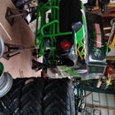
These shots shows my initial mock-up of the new wheels. I got it sitting level on my workbench using a car jack, then supported the new mods with jack stands so I could adjust the position of the new axle. I wanted to stretch the wheelbase a couple inches and widen it as well. This thing will be capable of doing 15+ MPH when I'm done, so keeping the center of gravity low and the wheels spread out to prevent rollover was a consideration.
The main point of this mock up was to get a good idea of where I'd be locating the rear axle in relation to the body. Once I was happy with where it would be sitting, the body would be coming off. Once the body is off, I'll have to go by my notes from this section to make sure everything ends up where I intended it.
Also, I adapated the stock front spindles to fit the new wheels. The stock spindles are 7/16" steel rod. I simply slipped a piece of 1/2" CPVC tubing over the spindle and pressed the 5/8" wheel hub over that. The tubing acts as a replaceable bushing and actually fits very nice and tight in both dimensions. I then spaced the wheel out using cut off section of the stock frame, which slipped tightly over the CPVC.
Step 3: Remove Body and Modify Chassis for Axle Placement


There are 9 screws holding the body to the chassis. Just unscrew those, remove the steering column and the body will pull right off.
As you can see from these pictures, there are three stock crossmembers in the rear that will now be in the way of my sprocket and axle. Using my disc grinder with a cutoff wheel, I cut them all out and set them aside for use as spacers on the front wheel spindles.
Step 4: Weld Axle Brackets in Place


Now that the stock crossmembers are removed, I welded the bearing hanger brackets onto the frame. I made sure to keep the center of the new axle at the same height as the stock axle. This way the ride height will be level. I did place the new axle 2.5" further back than the stock axle was, to stretch the wheelbase out for stability.
Once the axle hanger brackets are on the frame, I started assembling the axle with it's components. I basically just threaded the axle through the bearings and made sure to slide on the sprocket hub, the brake rotor hub and some lock collars.
Step 5: Fabricate and Weld Motor Mount Crossmembers


Now that rear axle is floating close to where it'll be, I needed to make up a place for the motor to sit. I opted to have the motor sit towards the passenger side of the vehicle to help balance out the weight of the driver. I cut and notched two pieces of angle iron to act as new crossmembers that I can bolt the motor to. I cut them to length and then used my disc grinder to cut out a radius to fit around the tube of the frame. Then I cut some slots into the angle iron to have a slightly adjustable position to mount the motor. Once I was happy with where it was sitting, I welded it to the frame.
Step 6: Fabricate and Weld Brake Caliper Bracket

The motor sprocket makes it go, this brake caliper will make it slow.
I adapted the mountain bike brake rotor by enlarging the holes on it to fit onto a 1" axle hub, which I also had to modify a bit. It was a bit tricky to get the rotor perfectly centered on the hub adapter, but it did come out pretty dang close in the end. I didn't want it to be off center too much, or it would hit the brake caliper as it rotates.
I made the caliper bracket out of some flat steel bar I had laying around the shop and just bolted the little caliper that came with the rotor to it. Now the caliper floats in just the right position to grab the spinning rotor and slow down the vehicle. This caliper will be connected to a lever in the cab via a piece of brake cable. Now all that needs done is cutting and mounting the chain and the rear is just about finished.
Step 7: Modify Front Crossmember to Fit Rack and Pinion Steering and Battery Box


Onto the front end modifications!
I had to put the body back on briefly to locate the steering column. This required cutting out the body a bit to fit. I marked on the frame where the steering column was to be centered and then took the body back off.
I bolted the rack and pinion to the steering knuckles and found that it was going hit the front crossmember. So I cut a section of the crossmember out and sistered a piece of 1" c-channel to it. I then welded bolts to the c-channel that the steering box can be fastened to.
While I was up here, I made a steel box to hold the dual 12v 20AH SLA Batteries and attached that to this same crossember. I did this to relocate the batteries as low as possible to keep the center of gravity low. The only thing I don't like about this position is that the batteries are now unsprung weight. I might revisit this and re-attach the battery box to the upper frame instead of the front crossmember to fix that issue, but for now it's been working fine.
Once those parts were attached, I put the body back on and ran the steering column through it. I attached the steering wheel with a quick release adapter so I can remove the steering wheel to prevent unsupervised joy rides.
I also had to modify the wiring a bit to reach the new battery location. That was just a matter of reconnecting everything how it previously was connected, just down underneath the vehicle. I ran a small piece of conduit along the frame and extended the wires through it down to the battery.
Step 8: Fabricate and Install Hand Brake


Turns out nobody makes a small handbrake for less than a couple hundred bucks, so I decided to make my own rudimentary lever. It's just some scrap steel, a couple of nuts and a spring that I had laying around the shop. I painted it red to help little drivers know its for stopping, then installed it on the floor of the cab. I ran a piece of brake cable under the truck and just crimped a ring terminal on the end to hold it on the lever. I will have to replace the brake cable every time I take the body on/off now, but they come in an 8-pack for cheap.
Step 9: Optional: LED Light Upgrade


While I was in here, I figured I may as well hook up new LED lights. These ones are 3" red halos with a white center headlight. They're designed to be used as fog lights on an actual car, so they're plenty bright enough for a go kart. I just hooked them to the stock wiring for now, but they could be brighter if I were to use a stepdown voltage converter and run them directly off the battery on their own circuit.
Step 10: Optional: Change Gear Ratios

My little buddy loves to help me work on stuff, so here he is giving me a hand with the gearing. Initially I put a 72t sprocket on the axle, which gave us a 7.2:1 gear ratio and theoretical top speed of around 16mph. This worked pretty well on flat, dry land, but we wanted a bit more torque on the low end. Here we are swapping out the 72t for an 84t sprocket. The 8.4:1 gear ratio provides quite a bit more low end power and brings the top speed down to 12mph, which I feel is much safer for a 4 year old. As he gets older, we can adjust gear ratios more to suit whatever it is we end up doing to this thing next!
Step 11: Have Fun


Get out there and enjoy yourselves! We've been running this almost daily and it's actually been problem free! I was anticipating a lot of trial and error to get it working properly, but it's be surprising how smooth it operates. This has definitely been one of our more fun projects and I can't wait to see where it goes next. Lithium power? More volts? Instant-on ESC? Follow me here and on Instagram to see what we're up to next!

Second Prize in the
Toys Contest


