

Introduction: Crazy Caterpillar - Arduino Robot W/Grove Joint & Infrared Sensor


My friend Steven, who is a Secondary School Teacher, asked me to design a lovely bionic animal as a training aid which could help make their study more interesting.
So I made the Crazy Caterpillar for her. The small worm has two heads. They can be controlled by two different IR remote controllers. They can crawl step by step.
Therefore, every two students can make and play with the caterpillar together. In one class, many caterpillars can be used. After class, they even can play an interesting game named A MAZING CATERPILLAR RACE with their own caterpillars. The fastest caterpillar will win and the team will get the reward.
Two player: Coordinate with partner, go go go...
Multiplayer: Coordinate with partner, to make the caterpillar move up and down effectively, go go go...
Step 1: List
Step 2: Hardware Connection

We use a tiny Arduino compatible board - Grove Joint as the controller here, which include 2 Grove connector.
And we have 2 Grove - Mini I2C Motor Driver to drive the 4 motors. Each Grove - Mini I2C Motor Drive can drive 2 motors, as there're 4 motors.
First of all, let'a make a different address of the Grove - Mini I2C Motor Driver, please refer to wiki of the driver.
As there's only one I2C connector on Joint, so a Grove - I2C Hub is needed.
About the Grove - IR Receiver, we connect it to the rest of Grove connector, which is D3 and D5.
Step 3: Software Works


Grove - Joint is an Arduino compatible board.
Let's download the code here.
- When you get to the github page, find a Download ZIP button, click to download the code.
- The code you downloaded is not an Arduino library, it's a sketchbook, which is include all the library the project need. Unzip the file you had downloaded from github, you will get a folder named CrazyCaterpillar-master
- Open your Arduino IDE, click File > Preferences > Sketchbook Location, browse to the folder we had mentioned above - CrazyCaterpillar-master. Then click OK to save it.
- Close and re-open Arduino IDE, click File > Sketchbook > demo, then the main code of this project is open.
- Select the right board (3.3V 16M 328) and port to upload the code. Refer to the image above.
Attachments

Step 4: Test IR Receiver
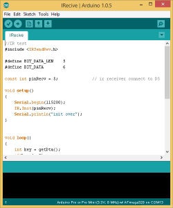
Open the code IRecive, upload the Grove - Joint, and open the Serial monitor @115200 baud rate.
Try to press a button in the remote, see if you can get a number printed at the monitor.
If no, maybe your remote is not supported, try another remote.
The number is the key of a button, you need to know the key of the button that used.
Step 5: Test Motor

Connect the 2 Grove - Mini I2C Motor Driver to Grove - Joint(with a Grove - I2C hub), and the whole 4 motors to the driver.
Open the code MotorTest, which is a simple code to test the motor. You will find thr 4 motors move forward for 100ms and then backward for 100ms, and loop.
If the motors don't move, please double check your hardware.
Step 6: Upload the Final Demo Code
Open the demo example, this is the code of the final project.
Upload the code to Grove - Joint.
Step 7: Design and Laser Cut

Laser Cut the board using the Design Drawing.
Attachments
Step 8: Make the Head1 of Caterpillar - 1


There are three parts of the caterpillar: Head-1、Body、Head-2、
There are six faces of the Head: Top、Bottom、Front、Back、Lift、Right
Make the Top face:Follow the third picture (PS: the small “ bone ” is used for fixing other boards, so you need to turn it 90 degrees )
Make the Front face:Repeat the steps of Top face
Step 9: Make the Head1 of Caterpillar - 2

There are two steps of the Bottom face:
1. Assemble the universal wheel
2. Fix the hinge
Step 10: Make the Body of Caterpillar


As illustrated in FIG.1, there are two parts of the electronic modules. One part needs to be put in the Head1, the other part needs to be put in Head2.
1. Put one part of the electronic modules in Head 1 and fix it as illustrated in FIG.2-3.
2. Fix the Touch latches as illustrated in FIG.3
Step 11: Make the Head2 of Same Steps

Repeat the steps to make Head 2 and fix the other part of electronic modules in it.
Step 12: Make the Body of Caterpillar


Follow the picture to fold the paper.
Step 13: Assemble All of the Part

Follow the picture to assemble all of the part.

Participated in the
Full Spectrum Laser Contest 2016

Participated in the
Make a Box Contest


