

Introduction: Creating a Simple 3D Model on Fusion 360 and Creating a Toolpath MYDIYCNC


Hello there,
Tory at MyDIYCNC here. Today I want to show you how to use a very useful piece of software from Autodesk called: Fusion 360. With this software you can create simple 3D Models, to elaborate and complex 3D models.
What I hope to teach you today is how to create a simple model on Fusion 360, and then create a tool path in which you can then run the G Code on your MyDIYCNC machine or another CNC machine.
Let's get started!
Step 1: Open Up Fusion 360, and Begin Creating

First of all, go ahead and install Fusion 360. After you have installed the software, open it up and move to the next step.
Step 2: Create Your Simple Model


Follow the directions for this step.
1. Select the drop down menu CREATE, we are going to use just a simple cylinder model.
2. Select the face of the model, the X and the Y axis are the RED and GREEN lines, and the Z axis is the BLUE.
3. Specify the diameter of your model, we are going to make it 3 inches.
4. Specify the height of your model, we are going to make in .5 inches.
5. With your model base created you can then modify it with a number of tools, we are just going to use the Fillet tool
to demonstrate, and give the model a little smooth curve to it.
Step 3: Save Your Model and Begin Creating a Tool Path


In this step we will now create our tool paths. Follow each direction closely.
1. Save your current Simple model to keep it on file.
2. Select from the drop down menu CAM, now you will enter into the Cam section of the program.
3. Select from the drop down menu SETUP,this will start a new setup for your tool paths.
4. First you will set your Stock Point, set it at the top bottom corner of the model.
5. Under the STOCK options you will define the size of your stock, L x W x H.
6. You also want to offset the model to the bottom of the stock instead of center of the stock.
Step 4: Creating a Tool Path CONTINUED


Continue creating your tool paths. Follow the directions.
1. Select from the drop down menu 3D Pocket Clearing, other options can be used but we will use this to demonstrate.
2. First in the tool path setup you want to select a tool, we must create a new end mill now.
3. Now you will enter in the specs of your new end mill, size, diameter, shaft, flutes, so on and so forth.....
4. After you have created your new end mill, you can move over to retract and safety heights. Just make sure and inspect that the heights do not conflict with the model.
Step 5: Creating a Tool Path CONTINUED


Continue to follow directions.
1. Now you will edit your passes.
2. Be sure to set machine shallow areas, as this will give a better quality cut.
3. Set your manual Step over to the correct specs according to your end mill size.
4. Set Direction the Conventional.
5. Press OK once all Specs are set. Now Fusion 360 will generate your tool paths.
Step 6: Post Process


Now with your tool paths generated you will take the last step which is the Post Processor.
1. Select from the drop down menu POST PROCESS
2. In the Post Process menu, you will select the MYDIYCNC Post, or what ever other post you are using.
3. Save the Post and VIOLA! You are done!
Step 7: Good Job, Well Done!

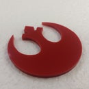
Nice Job!
You have successfully created a model in Fusion 360, created tool paths, and completed it with the post processor!
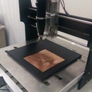
You can now use your G Code file that you have created, as you can see it is successfully loaded into FabCam. Creating a model and learning how to create tool paths can be easy, with some patience and imagination you can make anything! Be sure to look at my other tutorials here on instructables, and check out our site at MyDIYCNC.com
Thanks for participating guys! Enjoy the CNC world!


