

Introduction: 1kW Arduino MPPT Solar Charge Controller (ESP32 + WiFi)


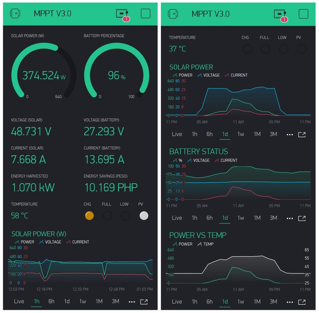


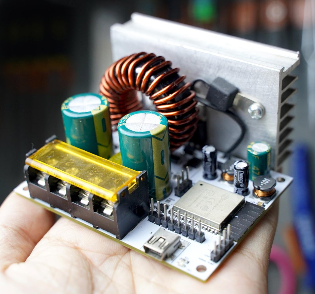
Build a 1kW WiFi MPPT Solar Charge Controller, equipped with phone app datalogging telemetry! (Android & IoS) It is compatible with 80V 30A solar panel setups and all battery chemistries up to 50V. The project is based on an Arduino ESP32 and runs on my Open Source Fugu MPPT Firmware! Total project cost is roughly around $25 (sourced from the Asian market). It is significantly cheaper than buying ready made $200 MPPTs
WATCH THE COMPLETE VIDEO TUTORIAL:
PCB Purchase Link:Click Me
G-DRIVE:Schematics, PCB, Codes, Parts Lists & Parts Links
What Is An MPPT And Why It Is Important To Solar Panels?
Maximum power point tracking (MPPT) is a technique used with energy sources with variable power, like solar panels, to maximize energy harvesting! An MPPT solar charge controller is an essential device for solar setups. MPPTs are intelligent DC-DC converters. They regulate current and voltage to safely charge batteries and power inverters. Aside from regulation an MPPT uses a clever algorithm that tracks a solar panel’s maximum power point. The proper explanation gets technical but the easiest way to put it
“Using an MPPT for solar, helps you gather the most energy your solar panels can provide”
High Efficiency Synchronous Buck Design
Synchronous buck based MPPTs are one of the densest and energy efficient designs. Premium commercial grade MPPTs use the same circuit topology. It turns out, you are not paying for the materials but rather for a company's R&D costs. Building one is cheap, but producing a proper design takes a lot of work.
One Of The First Tutorials To Uncover A Working Synchronous MPPT Design
For years, the DIY community has made several attempts on building a True Synchronous Buck MPPT but is often met with serious problems. This tutorial will walk you through on how I implemented a fix to the age old problems that has plagued most DIY MPPT attempts on building a high-power MPPT. It will also walk you through on building my 6-month tested beta MPPT design.
UPDATE FEED:
- (09/11/21) Support For 80V Battery Chemistries - The MPPT can be modified to support batteries up to 80V (12V/ 24V/ 36V/ 48V/ 60V/ 72V/ 80V), through a mod. Kindly visit 'step #38' of the instructable tutorial link. Read it carefully!
- (09/11/21) Support For Solar Panels Above 80V - The MPPT can be modified to support solar panel voltages above 80V. Step #39 will guide you how to achieve it. This is mod isn't for everyone, I highly discourage this mod!
(09/11/21) Updated Calibration Guide - Is your build giving slightly inaccurate values? I have added the calibration process in the programming step in this instructable.
(09/12/21) QR Code Fix - The QR code in the video is wrong. The QR code in this instructable was updated for the fix. Kindly refer to the QR code in this instructable.
(12/04/21) Constant Voltage (CV) Regulation Bug Fixed - The GitHub and Gdrive code files were updated for the Arduino code fix for the CV regulation bug fix.
Step 1: Project Specs

My goal was to build a DIY MPPT that I would continually use for my off-grid solar setup. It had to be good so I beefed it up during the design process. This included the use of a 16bit ADC for precision sensor measurement, a really fast dual core 32-bit microcontroller for quick system computations, implementation of a higher PWM resolution and the addition of a wide selectable range of PWM frequencies for switching optimization. There's also a bunch of telemetry options for IoT and a an opensource firmware that will be cross-compatible to my future MPPT builds.
TECHNICAL SPECS:
- MPPT Perturbed Algorithm With CC-CV
- 80V, 30A Input (Solar, Wind Turbines, PSU)
- 50V, 35A Output (Li-ion, LifePO4, Lead Acid & etc.)
- 98% Peak Conversion Efficiency (Synchronous Buck)
- WiFi & Bluetooth Blynk Phone App Telemetry
- Charger/PSU Mode (can operate as a programmable buck converter)
- 16bit/12bit Precision ADC Measurements (ADS1115/ADS1015)
- Automatic ACS712-30A Current Sensor Calibration
- Battery & Input Disconnect Recovery Protection Protocol
- LCD Menu Interface (with settings & 4 display layouts)
- Flash Memory (non-volatile settings save function)
- Settable PWM Resolution (16bit-8bit)
- Settable PWM Switching Freq (1.2kHz - 312kHz)
POWER CAPABILITY:
- 12V OUTPUT/ BATTERY - 420W @35A
- 24V OUTPUT/ BATTERY - 840W @35A
- 36V OUTPUT/ BATTERY - 1000W @35A (when safety unlocked 1260W)
- 48V OUTPUT/ BATTERY - 1000W @35A (when safety unlocked 1680W)
- 60V OUTPUT/ BATTERY - (mod required)
- 72V OUTPUT/ BATTERY - (mod required)
- 80V OUTPUT/ BATTERY - (mod required)
TAKE NOTE:
- The 80V input refers to the absolute Voc of your solar panel. Going slightly beyond this could potentially damage your MPPT. Take note that Voc and Vmp are two very different things.
- Kindly limit the current settings to 30A at the moment, the design has only been bench tested at an output of 48V 20A in PSU mode.
- As far as it goes, the charging mode has only been tested at 22V-27V 23A-19A continuous with an 8S LiFePO4 battery pack during peak sunlight hours last summer.
- Feedback on the design is much appreciated as I am new to switching electronics. I would be glad to rectify mistakes done in the tutorial.
- Firmware is locked to 1kW regardless of the theoretical power rating. This safety measure was done due to the lack of parallel MOSFETs and inductor wire thickness on this build. Regardless, I would have do conduct future tests in the future before unlocking the 1kW cap on this specific build.
- The project is limited with a maximum input current sensing range of 30A. Regardless, the output would be limited to an absolute output current of 35A due to the MPPT's buck core design.
- How can a higher output current be measured if we only have one 30A current sensor at the input? Due to a buck topology's characteristics, assuming input voltage is higher than of the output, input current is lower from the input than of the output. A simple formula was used to approximate the current at the output by using a single current sensor. This will be further explained in the tutorial.
- Why does it say 30A output at the video? The 35A tested inductor design had to be de-rated for safety reasons. The MPPT can possibly output 35A but for this specific project, the firmware is set to 30A by default. I am aware that the inductor's saturation current is different from the RMS current of the buck. Assumptions were done that the inductor's worst case saturation current is twice the tested current due to its powder core soft saturation characteristics. You can read more about this as you proceed to the write-up, some portions are yet to be updated as I am in the process of documenting the part 2 of the video tutorial.
Step 2: What's New? (Fugu MPPT V1.0)
My First Truly Stable Build
This is my 6th MPPT SCC design, I made 5 prototype before this. The build underwent 6 months of testing. My MPPT project is still hooked up to my 640W solar setup that has been powering my off-grid workspace ever since it was installed. I waited for months to ensure that the design is free from problems before I released it for open sourcing. Today is the day!
The Inspiration For The Project
When I bought some solar panels a few months back, I was looking for some MPPT solar charge controllers only to find out that they were expensive! Being the tinkerer that I am, I decided to build one on my own. I knew the materials would be cheap but the design process would be a lot of work. I searched on different journals and tutorials. One that really stood out was Open Green Energy's step by step design tutorial! (ARDUINO MPPT SOLAR CHARGE CONTROLLER) I read the entire tutorial, it was impressive! He did mention the issues that he encountered from his build and why the project was never considered finished. I tried to think of ways to solve these issues, thus the six different board revisions that lead me to my final problem-free build.
Step 3: My Earlier Prototypes


My old designs were based on a homebrew Arduino Nano using an ATmega328P-AU microcontroller IC, similar to what open green energy was using. I discovered that the Arduino Nano had a ton of limitations ever since I started designing higher power MPPTs. On the other hand, they were sufficient to lower power MPPT designs.
Some of my prototypes had lower specs and other had higher specs to than what I used on my stable build. I played around with different tradeoffs trying to find a proper balance between cost and performance.
Why I Stopped Using Arduino Nano For High Power MPPTs:
- Arduino Nano is an 8-bit microcontroller it is relatively slow at crunching math operations. Remember an MPPT is smart and glorified SMPS converter (buck converter in out case). It needs to be able to crunch a lot of numbers while running a bunch of processes. These processes include, regulation, MPPT tracking, safety protection, telemetry, metering and a whole lot more. While I find the Arduino Nano sufficient at processing speed, it does a poor job at being fast at regulation, if you input voltage ramps up the output has a relatively slow response to limit voltage or current. I made a way around this, on my earlier prototypes. Whenever the Arduino Nano can't keep up and exceeds the parameter limits, the MPPT charging stops as it tries to recover. This kept on triggering often and disrupts my energy harvest. On the next step I'll show you a cheaper and faster alternative.
- The ATmega328P used in an Arduino Nano and uno has a 10-bit ADC. This are known to most as analog pins. 10-bits means there are 1024 values it can represent from 0V to 5V (5V being the default voltage reference). When the ADC pins are used with voltage and current sensors design for a wide range of voltage (ex: 80V 30A), you only have 1024 values to represent 0V-80V and 0A-30A. This gives us a sensing resolution of 78mV for voltage and 29mA for current. This means you have a very coarse way of detecting voltage and current.
- Arduino UNO/ Nano is also limited to an 8-bit PWM resolution and a maximum frequency of 62.5kHz. The frequency is not bad but an 8-bit PWM resolution simply isn't enough if you want good performance. 8-bits of PWM resolution gives you 256 unique values on the duty cycle scale. When you apply this to a high power MPPT or buck design a single shift in the value would lead to large steps in voltages. This can be compensated by using larger capacitors as a buffer and speeding up the loop cycle processing time on an MCU based SMPS circuitry.
- At the end of the day there's a cheaper alternative called the ESP32. On the next few steps I will explain why I resorted to using it.
Dual Current Sensor Version:
- One of my earlier protoypes used a dual current sensor configuration, one at the output and one at the input. This was essential since a buck converter has a different current from the input from output. In a buck type MPPT, the current is usually higher at the output than of the input. This meant I needed two different current sensors optimal for the two different ranges. I tried the ACS712-30A, ACS758-100A, LEM DLSR50-50A and etc... They all worked well, but they also made the builds more expensive.
- A single current sensor at the input was more than enough. You can simply derive and approximate the current output by getting the input current and input voltage and equate it to the output voltage and output current, while solving for the output current. (Three given values, one unknown). This comes from the assumption "Power In = Power Out". This has one single disadvantage. All buck converters have power losses. The current at the output derived from the input current sensor will not be accurate as the power losses are not taken account of. But remember at the end of the day, you are only using the output current for limiting the charging current and for coulomb counting. The power at the output will always be lower than the power at the input in a buck converter. This mean is I set my charging current a lets say 30A, the actual current you will be getting is less than 30A (maybe around 29.5A lets say). Needless to say, you will not suffer from a tad of current discrepancy at the output.
A Better Current Sensor:
- The ACS712 has been one of the most popular current sensors used by tinkerers. Simply because it is cheap, effective, can sense current in both ways, has isolation and is easy to use. But it isn't perfect. For one, it is noisy! There's so much noise even when you are measuring a purely flat DC circuit (battery and load resistor), the values can be a tad twitchy. If you are using modules you can decrease the noise by replacing the filter capacitor with a larger one as stated by the Allegro's datasheet to limit the bandwidth. The mod will be explained later. Another problem is that it uses the 5V Vcc pin as a voltage reference, so if your 5V regulated supply line changes in voltage, the analog output of the current sensor changes as well. This was a big turn off and requires attention during the design process. Since it is hall-effect based, any sort of EMI around the chip will cause the values to twitch, when designing an MPPT with the ACS712 near an inductor, some sort of magnetic shielding is required to keep it stable.
- THE UPGRADE! On one of my recent prototype builds, I used an industrial grade current sensor called the LEM HLSR50! It was one of the best I have tried on an MPPT. It had all the good things of the ACS712 and none of the bad things. It can measure bi-directional currents of 50A (125A peak), it was isolated and it was also easy to use. But this time it had very little noise! The analog output barely twitched on a pure DC test. It has an internal voltage reference so the analog output was independent from the 5V Vcc line. It also had a separate pin for the voltage reference. This meant a differential ADC can be used, a differential ADC eliminates the need of computing for the zero point in a bi-directional current sensor. This also meant that the HSLR50 barely required sensor calibration. It was magnetically shielded too! EMI was barely a problem, even putting it close to a neodymium magnet barely affected the performance unlike of the ACS712. There was only one down-side, the price. From where I live it's only $6 at e-gizmo, but from the US or other western countries it costs around $16 from DigiKey. This was the main reason why I didn't use it on my current build. Perhaps, you'll see it on my futures builds someday.
If you're interested to see my build diary, I casually post project porotypes on my personal facebook account. There includes all the other projects I haven't or never made an instructable tutorial or video tutorial for.
Step 4: WARNING

BORING DESIGN EXPLANATION AHEAD! SKIP TO STEP#11 IF YOU ARE ONLY INTERESTED IN BUILDING THE MPPT PROJECT.
- The following steps will explain a lot of things covered by the design process of the final schematic.
- Forgive me if I will butcher a bunch of technical terms into laymen's terms. I would like to speak casually on this tutorial to make it easier for others to understand. (Ex: I will use the word MPPT to refer to Maximum Power Point Tracking Solar Charge Controller or MPPT SCC. Yes some people get triggered from not using terms like these properly).
PROJECT LESSON PREREQUISITES:
This tutorial will skim through these concepts required in designing an MPPT solar charge controller. If you have trouble understanding some of these concepts from this tutorial, you can google these topics to search for much more detailed explanation to fully understand the concepts involving this project.
- ESP32 MCU basics
- ESP32 MCU PWM resolution and frequency
- The MPPT algorithm concept
- Photovoltaic cell IV curve
- External ADC basics
- RC filters and bandwidth
- Noise rejection methods
- Voltage sensing using voltage dividers
- Current sensing using hall-effect based sensors
- Synchronous buck converter 101
- Synchronous buck backflow control
- Basics of half-bridge MOSFET drivers
- N-channel MOSFET operation and characteristics
- Advantages of low on-resistance N-channel MOSFETS
- Reverse blocking MOSFETs
- Concept of ORing diode emulation using N-channel MOSFETS
- Basics of inductors
- Toroidal core inductor design
- Methods of efficiency optimization in SMPS
Step 5: How MPPTs Work Simplified (For Engineer Dummies Like Me)
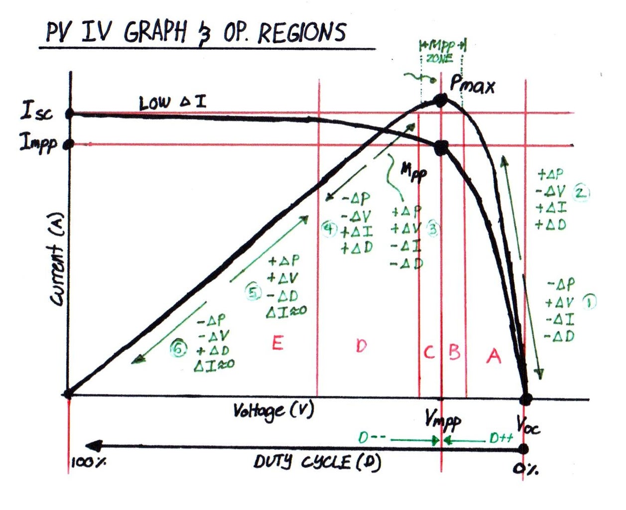

This step deserves a separate tutorial and will be included in part 2 of my video. For now I will give a quick no-brainer explanation of the Photovoltaic IV Curve.
How MPPTs Work:
When I was getting into building my first MPPT, I couldn't get a grasp of how the Photovoltaic Cell's IV curve behaves and its relationship with a buck. Text books will give you a bunch of terms that would alienate a lot of people. I understood some of them as they were taught on our engineering courses, but some were still new to me. While Part 2 of the video isn't out yet, here's a cool experiment that I did that is included on the story telling video I plan to make based on a real life experiment experience.
I only got an grasp on how it works when I built an experimental and raw buck converter with a solar panel as its input, a variable potentiometer for controlling the duty cycle (no voltage feeback) and used a nichrome as a load at the output. I connected the an LCD wattmeter in between the solar panel and the experimental buck's input. As I turned the knob up (increasing the duty cycle of the buck), the power readout at the LCD wattmeter started to increase from 0W to 20W I continued turning the knob to further increase the duty cycle, the power readout kept on increasing rapidly up to 305W, it was when the power started to decrease slowly as I continued turning the knob to further increase the duty cycle. As I continued to reach the end of my knob (reached 100% - max duty cycle) I got 0W of power, almost 0 volts and 9A of current at the input. Weird right? High current but almost no power! Okay, now that we have 0W of power while the knob is turned all the way up, I started to decrease the duty cycle by turning the knob backwards, the wattmeter showed an increase of power again from 0W to 305W again, as I continued to decrease the knob the power started decreasing again from 305W to 300W. So I turned it up again (back and fourth) to maintain 305W. As the sun rises higher, the power started to change, so I had to move the knob back and fourth to sweep for the highest power I could get from the panel. It was like a game of see-saw. When the sunlight's intensity changes, I had to sweep back and fourth to get the highest power I could get from my panel.
This is how MPPTs work! Me turning the knob, to control the duty cycle of my buck regulator while comparing the readings to get the highest power from the panels, is the most basic explanation how MPPTs work. The knob represents the duty cycle control of the MPPT's buck converter. The wattmeter and I represent the feedback of the MPPT's system. MPPTs work in a very similar way, but replaces the human turning the knob clockwise and counterclockwise with a machine such as a microcontroller. This way humans are not needed to constantly tune that knob to get maximum power.
In MPPTs this type of Power Point tracking is called the perturbed algorithm, also known as the hill-climb algorithm. The MPPT device (a glorified, intelligent buck converter) sweeps the duty cycle back and fourth while comparing the power harvested while keeping it close to the highest possible power that can be harvested from the solar panels.
I will be updating this explanation when I get the proper words for it. In the meantime, this article will help you get a much better understanding of the technicalities of the IV curve graph. (Read this Article)
Step 6: Highly Efficient Synchronous Buck Technology

A lot of people are new to this but there is a much more efficient buck topology that exists. This is called Synchronous Buck Converters and are widely used in high-end commercial grade MPPTs. It sounds fancy and complex, but design and cost wise it is actually simple and cheap (difficult to get going though). Luckily this guide will show you how to get one working as we will be implementing this on our MPPT.
Two Buck Regulator Designs:
- Asynchronous Buck Converter
- Commonly Used
- Typical Efficiency (75-87%)
- Not the most energy efficient
- Notable power loss due to the presence of a diode
- Very easy to implement
- Synchronous Buck Converter
- Less Common
- Typical Efficiency (88-98%)
- Extremely energy efficient
- Power loss reduced by replacing the Diode with a MOSFET
- A nightmare to implement without prior knowledge
Prerequisites:
This step will explain the operation of the two different buck converters with an assumption that you already have learnt on the basics of buck converters and N-channel MOSFETs. If you haven't, kindly google "how buck converters work" and "how N-channel MOSFETs work". This step will make more sense when you get to read on them both.
Buck Converters In General
Buck converters are regulators that converts a higher voltage input to a lower voltage input. It's not the other way around as that would be called a Boost Converter. Unlike linear regulators, like the infamous 7805 IC, a buck regulator does not shed off voltage and current for regulation through heat. Whether it is a Buck, Boost or Buck-Boost, these regulators do its best to conserve power (Power In - Power Losses = Power Out). Notice the " minus Power Losses", despite being efficient, a buck regulator will never achieve 100% efficiency and will still have losses, not unless you live in a utopians world. Also, a buck regulator creates a current amplification effect (sort of), as the voltage decreases at the Buck's output the current it could provide at its output can be greater than of the current provided at the input. A buck converter is a form of switching regulator, where it uses a PWM signal, some transistors, some capacitor, an inductor and a feedback to regulate voltage and current.
Asynchronous Buck Converter - Example
The first thing that pops into peoples minds when the word "buck converter" comes up are those cheapo blue board LM2596 Buck Converter Modules. These modules that most of you are familiar with are based on the less efficient Asynchronous Buck Converter topology. It uses a diode and a MOSFET or BJT (which is inside the LM2596 chip with the PWM feedback driver). These things typically reaches an average efficiency of 75-85%. Aside from having a lower efficiency rating, you will also notice that those modules heat-up easily even when used with its advertised current rating. This heat-up is caused by thermal dissipation caused by the lack of efficiency (switching losses, conduction losses & etc...).
Asynchronous Buck Converter - Why it's inefficient?
Don't get me wrong, asynchronous buck converters are still efficient compared to linear regulators. But its efficiency could be better! The reason why these Asynchronous Bucks are incapable of reaching efficiency ratings close to 98% is due to the losses incurred by the presence of a Diode. The diode is essential to a buck converter as it prevents current from flowing back. There is something called a forward voltage drop (Vf), most silicon based diodes have forward voltage drops ranging from 0.4V-1.2V. That's it? Well it doesn't sound much, but when you are approaching high-power electronics territory, that mentioned voltage drop causes a ton of power losses. The drop in voltage from the diode isn't just a drop in voltage, it results to heat and heat is a useless form of energy in electronics. Think of it as having a leak in your water pipes at home, you wouldn't get the same amount of water volume from what your meter measured, as a result you lose water and pay a higher water bill. Similar to solar setups, waste power and you wouldn't get to harvest the most out of what your solar panels can produce.
Synchronous Buck Converter
The answer to the Asynchronous Buck's lack of efficiency is a slight mod to the Asynchronous buck. By simply replacing the diode with a MOSFET, the voltage drop caused by the diode is nearly eliminated. Why a MOSFET? Unlike BJT transistors a MOSFET does not have a diode's voltage drop when it is activated. When a MOSFET conducts, by applying voltage across the Gate and Source pins, the MOSFET conducts. You can think of MOSFETs as a mechanical switch. They're really fast too! Think of Marvel's Flash pushing a light switch on-and-off in nano seconds. Now that we've solved that voltage drop from the diode problem, what's next? It is a common practice that N-channel MOSFETs are to be used and not P-channel MOSFETs. MOSFETs have something called Rds(on), also known as the on-resistance. When the MOSFET conducts it behaves like a resistor now, and resistors also causes voltage drops too. N-ch MOSFETs have immensely lower on-resistances compared to P-ch MOSFETs. As a result the N-ch MOSFET has a SIGNIFICANTLY lower voltage drop effect compared to using a diode (most of the time). Now we have lesser power losses dissipated as heat. Operation is simple, when Q2 turns on Q3 turns off and when Q3 turns on Q2 turns off. Of course, deadtime must be implemented in order to prevent Q2 and Q3 from turning on at the same time, causing a quick short (cross-conduction). Easy? No, there's more to it!
Synchronous Buck Converter - The Challenge!
Now there two main challenges in a Synchronous Buck. Now that we have replaced the diode with a second MOSFET, a new problem needs to be solved, mainly on switching them properly. The reason why Asynchronous Buck converters are easy to implement is because the diode, without any fancy circuit or code, automatically blocks current from flowing back. The MOSFETs on a Synchronous Buck on the other hand needs to be switched in sync with each other otherwise it would burn, thus the name Synchronous.
The first problem would have something to do with properly triggering the N-ch MOSFETs. Q3 is not a problem as the drain is tied directly to the ground. A simple totem-pole driver would be enough to switch the gate by providing a voltage between the gate and source pin of Q3. Q2 on the other hand is on top and its source pin is tied to the drain pin of Q3. This configuration is called a half-bridge. To properly switch Q2 a MOSFET driver must be used, specifically one that has a charge pump. This may not make sense to others who are unfamiliar yet to the importance of having a ground reference. A charge pump uses a capacitor to charge upon intervals while having a totem pole driver on the high-side MOSFET Q2 for switching. This ensures that the MOSFET gets the voltage it needs to switch-on entirely. While we know that MOSFETs can behave as switches, MOSFETs can behave as variable resistors too (operating in the active region). This happens when the MOSFET is provided with a lower voltage across the gate and source pin from the specified Vth (threshold voltage). The charge pump MOSFET driver ensures that the MOSFET saturates and gets the voltage it needs to fully conduct and have the lowest possible on-resistance for lesser power losses in the buck (Vgs are usually rated at 10V).
The second problem is the infamous low-side burning MOSFET present in almost all DIY synchronous buck MPPT builds. This is caused when the low-side MOSFET Q3 fails to emulate the diode it has replaced from the asynchronous buck. You can read more on this on the next step, I allocated a separate step for this since it deserves attention.
Synchronous Buck Converter - As a Asynchronous Buck
Fellow engineers would raise probably raise an eyebrow upon reading what I have written a few sentences back, as I have failed to mention that MOSFETs actually do have diodes inside them. Notice how there is a diode in parallel to the MOSFET's drain and source pins. This is called a "Body Diode". It has something to do with the MOSFET's physical construction and material contents. When MOSFET Q3 is turned off indefinitely, the Buck behaves as an Asynchronous Buck. But when you switch it in sync, the MOSFET Q3 conducts and provides a lower resistance path thus it behaves now as a synchronous buck (now you get a lower voltage drop effect). You can continuously turn Q3 off and turn the synchronous buck to an asynchronous one, but there's no point in doing that.
So It's Simple, Right?
Yes and no, hahaha! The implementation is quite simple but the proper process of operation (without going kabooooom!) isn't as straight forward as you think. To my surprise this is something you wouldn't find in your college text books but rather found in academic journals, semicon application notes and design guides. Open green energy was the only instructable user to provide a DIY friendly guides to the DIY world, but even he had some troubles too in getting his to work without problems. For years synchronous buck converters have been a trade secret in the industry as very few electronics enthusiasts share detailed guides on how to properly get these things working. Luckily it is our job as electronics engineers and tinkerers to shed light on this design without blasting enthusiasts with engineering heavy jargons. In the following steps I will show you how we fixed common problems with DIY synchronous buck MPPTs through a collab with my colleagues and Open Green Energy.
Step 7: Solving the Burning Low-Side MOSFET Problem


Open Green Energy's Problem:
"After lot testing we observed that MOSFET ( Q3 ) in ver-3.0 design is burning repeatedly. We tried to modify the existing software but not find any satisfactory result."
Open green energy wrote one of the most detailed MPPT tutorials present, mentioning not only the things that went right but also mentioned the issues with his attempt just like any good and honest engineer would. Hands down! This really helped us all to collaborate with each other to fix and share the design. I had also encountered this problem with my earlier builds shown from one of the previous steps. It took me months to figure out the culprit that has been haunting us all for years.
The second problem stated from the previous step is the infamous low-side burning MOSFET present in almost all DIY synchronous buck MPPT builds. This specific problem of open green energy and mine are exactly the same and was solve through code. This is something I have not read on anything yet up to date, but discovered through a bunch of lab tests and analysis on my workspace. There are some papers that explained this but they're either filled with a ton of jargons or does not specify this issue directly. The write-up below will explain everything.
Let's Explain The MOSFET Driver First
Before I get to the solution to the problem, I need to explain how the MOSFET drivers work to avoid confusing you all. The well known IR2101 and IR2110 drivers are something I call raw logic MOSFET drivers. You have two logic inputs HIN and LIN for controlling the switching at the high-side and low-side MOSFET (Q2 and Q3). When HIN is HIGH, Q2 is turned on and when HIN is low, Q2 is LOW. When LIN is HIGH, Q3 is turned on and when LIN is low, Q3 is LOW. This requires two PWM complimentary signals for buck operation. This chip gives you more control over the switching as you have control over the deadtime duration as well. I liked this chip because I have direct independent control over the Q2 and Q3. I used this on my first prototype version and I stopped using it because I feared it would make the explanation on this educational tutorial much more complex as you would have to deal with MCU timers that are not code friendly to Arduino Users.
The easiest MOSFET driver to use is the IR2104 IC, which open green energy used as well. Let's focus more on this now since it is what I'm using on my latest build. The IR2104 has a built in deadtime function, making the coding process a lot easier. IR2104 has logic input pins name IN and SD. IN is the input logic for the PWM signal for switching and SD is an enable pin. SD is simply a pin that overrides everything. When SD is LOW; Q2 and Q3 both turns off regardless if there's a PWM signal present at IN. When SD is HIGH, either Q2 or Q3 will turn on, depending on the IN pin logic state. When IN is HIGH; Q2 is HIGH and Q3 is LOW. When IN is LOW; Q2 is LOW and Q3 is HIGH. What does this mean? Well, now we only need 1 PWM signal to switch both Q2 and Q3 inversely, thus reducing the need for two complementary PWM signals. This means the higher the PWM duty cycle %; the longer Q2 switches on and the shorter Q3 switches on. On the other hand, the lower the PWM duty cycle %; the longer Q3 switches on and the shorter Q2 switches on. At this point some of you are probably getting a clearer picture of what the problem may be.
The Problem:
As it turns out, this is caused when the low-side MOSFET Q3 fails to emulate the diode it has replaced from the asynchronous buck. In controlling our buck MPPT design we provide a PWM duty cycle of 0-100% to the IR2104. Remember when I said "the lower the PWM duty cycle %; the longer Q3 switches on and the shorter Q2 switches on", at some point Q3 (the low-side MOSFET) acts like a short and no longer acts like the diode it tends to emulate from the asynchronous buck counter part. There is a specific PWM duty cycle floor value that you cannot go lower to, otherwise Q3 would start to heat-up. (more explanation in a while)
The Solution:
There are two solutions to this problem (hardware vs. software), Either to implement an application specific MOSFET driver IC for synchronous buck converters equipped with flowback current control (Analog Devices offers a ton of them) or simply use the old IR2104 design and fix it through code. Obviously I went with IR2104 design and fixed it with code since the IR2104 is dirt cheap and isn't anywhere the $10 price tag of a specialized chip for synchronous buck drivers.
I have discovered that there is a specific floor value for the PWM duty cycle % and should never be 0% or anywhere below that specified PWM floor value when a battery is connected at the output. So what is the PWM floor value I am referring to? I came up with a simple formula which I implemented to the open source firmware I wrote as well.
- PWM Floor Duty Cycle = (Output Voltage / Input Voltage) * 100
This means that the lowest possible PWM duty cycle should never be lower than the "PWM Floor Duty Cycle". The formula takes the output voltage and input voltage ratio to compute for the ideal unloaded PWM duty cycle required by the buck to output a voltage matching the voltage of the battery connected at the output. When PWM signal has a lower duty cycle than the computed PWM floor value, the current flows in reverse and causes Q3 to conduct when it isn't supposed to be conducting. So instead of charging the batteries, you are actually draining it. As you deviate to a lower PWM signal from the computed PWM floor limit, the reverse current Q3 experiences gets higher and higher causing it to burn. In the code the SD pin of the IR2104 is turned LOW when the PWM goes below the computed floor limit to ensure Q2 and Q3 never turns on at this state. You will notice that "PWM Floor Duty Cycle" is named as PPWM and " PPWM_margin*pwmMax " was added, this was to limit the maximum allowable PWM duty cycle since charge pump MOSFET driver like the IR2104 cannot operate at 100% duty cycle due to its IC design. It also turns the duty cycle % to an integer value to which the anlogWrite or ledcWrite function accepts.
- PPWM =(PPWM_margin*pwmMax*voltageOutput)/(100.00*voltageInput);
- PPWM = constrain(PPWM,0,pwmMaxLimited);
- PWM = constrain(PWM,PPWM,pwmMaxLimited);
- ledcWrite(pwmChannel,PWM);
- buck_Enable();
The constrain function in the Arduino limits the PWM signal from going above the ceiling limit as well as from going below the floor limit. The function "ledcWrite(pwmChannel,PWM)" is the ESP32 equivalent of an analogWrite of an Arduino Uno/Nano, the function is used to set the PWM signal at the GPIOx pin. There's a lot of codes in between the lines above, I just wrote the most important ones to highlight the fix solution.
Step 8: Solving the PV Backflow Current Issue

The Problem:
There's is something called a "body diode current leakage" in both synchronous and asynchronous buck converter topologies. This problem has been present in most DIY synchronous buck MPPTs I've read on, up to this date. There were attempts to fix the the high-side reverse blocking MOSFET but often ended up not switching Q1 properly. Notice, regardless whether you turn Q2 on or off, the presence of a diode inside the MOSFET Q2, causes current from the batteries to flow back to the solar panels when the input voltage is less than the output voltage (Solar Panel Voltage < Battery Voltage). This happens when solar panels produces lower voltages at dusk, dawn and at night-times. We are aiming for the highest possible efficiency, adding diodes at the input is the last thing we want. We need a solution!
The Expensive Solution:
This issue can easily be solved by a high-side N-channel MOSFET driver or something like an ORing MPSFET driver. I deviated away from this option as the driver chips required for this solution are rare and expensive.
The Cheaper Solution:
This is can be solved by adding a diode at the input (before Q2) to prevent current from flowing back, this is applicable to all buck topologies. But, remember from the previous steps I mentioned? Diodes cause voltage drops that leads to power losses! So again, we need to replace the input diode with another N-channel MOSFET, this time connected in reverse of Q2. This is called a reverse blocking MOSFET configuration. When Q1 and Q2 have body diodes opposing each other, current can no longer leak both ways, not unless we turn both MOSFETs Q1 and Q2 on. Now the challenge is to properly turn that newly added Q1 on and off. Clearly we can't just apply voltage at Q1's gate pin, since it is positioned at the "high-side" and far away from the ground. To fix this problem, we're dedicating an isolated DC-DC converter for it to be switched with.
The isolated DC-DC converter I have chosen is B1212S component by EVsun. With a cost of $2 per piece, it is cheaper than buying a dedicated application specific high-side MOSFET driver (ex: Analog Devices, TI & Maxim Chips). While another IR2104/IR2101 can be used, the isolated DC-DC converter & MOSFET combo has a slight advantage of being capable of operating at 100% duty cycle.
The isolated DC-DC converter creates an isolated potential difference between the source and gate pin of Q1. R37 is a pulldown resistor that bleeds out the gate charge of Q1 whenever no power is provided at the input of U2. The PV backflow prevention unit as a whole is switched by Q4. When GPIO27 releases a HIGH signal, Q4 conducts and provides a path for current to power U2 (the isolated DC-DC converter). When U2's input is powered, U2's output releases an isolated voltage of 12V and is supplied to Q1's gate and source pin, thus powering Q1 and closing the path from the Vin and Q2's drain pin. Turning GPIO27 to low results to the opposite of everything I said and turns off Q1.
My implementation was simple but barbaric. Response time for turning Q1 has not been measured quantitatively but I can assure you it is fast enough. Regardless leakage of current back from the panels isn't that high in the first place. This was just a feature needed to prevent draining the batteries during night. I understand that a better implementation would be to leave U2 turned on all the time while having an isolated totem-pole MOSFET driver chip to switch Q1. But hey it works!
But Solar Panels Have Diodes Inside Them? Right? Right...?
While solar panels can convert sunlight into electrical energy, it can also absorb energy back when the solar panel's voltage is lower than the battery's voltage. Batteries feeding current back to solar panels? Yes it can happen! There are two types of diode positioned inside a solar panel. One are the bypass diodes, which eliminates the hot-spot phenomena which can damage PV cells (not our concern) and the other is the blocking diode, the diode that prevents current from chargers and batteries from flowing back. As it turns out, after checking my monocrystalline solar panel's rear box, to my surprise it doesn't have blocking diodes installed. I did some digging and found out that modern day solar panels does not include blocking diodes as it causes power losses. Instead it has somehow become a modern day standard that the diodes are to be installed in the Solar Charge Controller.
Step 9: Why I Am Using an External Precision ADC (ADS1115 - Texas Instruments)


ADC In An Arduino Nano
The ATmega328P used in an Arduino Nano and uno has a 10-bit ADC. This are known to most as analog pins. 10-bits means there are 1024 values it can represent from 0V to 5V (5V being the default voltage reference). When the ADC pins are used with voltage and current sensors design for a wide range of voltage (ex: 80V 30A), you only have 1024 values to represent 0V-80V and 0A-30A. This gives us a sensing resolution of 78mV for voltage and 29mA for current. This means you have a very coarse way of detecting voltage and current and your voltages and currents could possibly jump with intervals of 78mV and 29mA.
ADC In An ESP32
The ESP32 has a built in ADC of 12-bits, this gives you 4096 values to represent your voltages and currents. That is four times higher than of the Arduino Uno/ Nano! For an 80V 30A setup, we get a voltage sensing resolution of 19.5mV and a current sensing resolution of 7.32mA. This is a far better voltage and current sensing resolution from the Arduino Uno and Nano! The ESP32 has a faster processor too! In terms of regulation, it will be able to poll faster as well, making it more responsive. But there is one downside! The ESP32 is known for having a bad ADC! It has a non-linear ADC response. This means the ADC is not that accurate for representing the voltages between 0V and Vref. It will suffice, but I did not want to settle with this. The solution?
External Precision ADC
The solution is to use an external precision I2C ADC! The one that I have chosen is the ADS1115 or ADS1015 by Texas Instruments. Why bother use an external ADC? These external ADCs were designed for a specific purpose, and that is to serve only as an ADC and nothing more, and it does its job extremely well! Notice how sensor values twitch unexpectedly when you connect them to an Arduino Uno? Try using an external ADC, you will notice that values barely ever twitch unexpectedly.
The ADS1x15 ADCs has a built in internal voltage reference. This means your analog value readings are independent from your ADC's Vcc. This makes it less susceptible to a system's supply line noise. It has a built in programmable Op-Amp, which means you can select a variety of gains. And most importantly the ADS1115 has a 16-bit ADC resolution! 16-bits for 860sps! 16-bits would give you a 65,5536 to represent your voltages and currents! This is 64 times better than and Arduino Uno's ADC. For an 80V 30A MPPT setup, we now have a voltage sensing resolution of 1.22mV and a current sensing resolution of 0.457mA! It's insane!
Should I go with the ADS1115 or ADS1015?
The big question is, which one do I need? Despite having slightly different specs, both chips are cross-compatible with Adafruit's Arduino ADS1x15 library. Do I get the ADS1115 with 16-bit resolution and 860sps speed or the ADS1015 with 12-bit resolution with 3,300sps speed? As mentioned in the video I have tried them both. ADS1115 was unnecessary for this build, it has a resolution I barely needed for 80V 30A. I went with the ADS1015 for the entire project's testing and documentation.
Why The 12-bit ADS1015?
ADS1015 has a 12-bit ADC resolution, same with the ESP32's 12-bit ADC resolution, why choose the ADS1015 still? The answer is stability. Remember when I made different revisions of the board. I have tried the Arduino Nano, Arduino Uno and ESP32; all their ADCs were not as stable as a dedicated external ADC such as the ADS1x15. Even when unlocking the ATmega328P and ESP32's internal ADC Vref (a mod for stability), it was nothing compared to an external ADC. Remember that now we are using a higher PWM resolution, we now need to sense minute changes in voltages and currents for the MPPT perturbed algorithm to work flawlessly. Slight noise and twitches in sensor readings heavily affects the MPP tracking. An external ADC is the way to go!
Step 10: Choosing an MCU (Why I Chose the ESP32 Over an Arduino Nano)


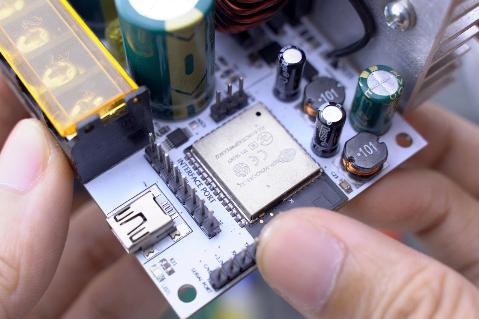
Some of you are probably familiar with the ESP32. There are two main version of it, the ESP32 Dev Board and the WROOM32 ESP32 Module. In terms of pins and specs, they are exactly the same. The dev board on the other hand has a USB port for programming, while the WROOM32 is a standalone MCU without a USB port. For a WROOM32 to be programmed via USB you need an external USB-TTL UART interface such as the CH340C. The ESP32 Dev Board has one, built-in to the board. Why did you go for the WROOM32? Mainly because of raw cost and space. Notice how I bought a reel of WROOM32s in the video, I bought 50 pcs of them for $1.80 each! They're cheaper than $5-$10 ESP32 Dev Boards. Second is space, the WROOM32 is tiny! Without expanding those SMD pads to THT pins, you can build a smaller project with it.
I've explained this in the previous steps but incase you have missed it, here's the summary:
- The WROOM32 module is only $1.80 from where I live.
- It is Arduino Compatible, you can use it like any other Arduino!
- ESP32 is a very fast and powerful 240MHz 32-bit dual core microcontroller
- It has built in WiFi and Bluetooth BLE, so you don't have to buy expensive modules
- It has a maximum of 16-bit PWM resolution
- It has a 12-bit Internal ADC (we won't be using)
- Has a low power core for low-power processing
- Capacitive Touch Pins
- Has a built in DAC
- The list goes on and on!
ESP32 - Why I Specifically Chose It:
- For $1.80, it was cheaper than an Arduino Nano and is equipped with specs that surpasses it in all ways!
- The most important part for me was the 16-bit PWM resolution. A higher PWM resolution is much more favored in a buck converter based MPPT. The higher the resolution, the finer the voltage and current steps would be. It is adjustable, the lower the PWM bit resolution, a higher PWM frequency can be achieved! (will explain more on this later).
- When I said it has two cores, yes you can run two independent processes while sharing the same recorded variables in two independently running codes. An MPPT has a ton of algorithms that should never be bothered. This includes voltage and current regulation, MPP tracking and protection protocols. WiFi telemetry for example takes 500ms of processing time to send. Combining WiFi telemetry on the same core with the main system processes would make the MPPT dangerous and less responsive. By allotting a separate core for the WiFi, I was able to get 9ms per loop cycle for the MPPT core.
- WiFi and Bluetooth also a big bonus for the price as well
- Processing speed: This thing is extremely fast! Take my words for it
ESP32 - PWM Resolution & Frequency:
- AVR MCU based board like the Uno and Nano were challenging in setting the PWM timers.
- ESP32 has library that simply asks for the PWM bit resolution and PWM frequency you need, and the rest is magic as you can use almost any pins for that specific PWM settings.
- Take not that the are limits
- For a 16bit PWM resolution, a maximum of 1.22Khz PWM can be achieved
- ..........
- For a 12bit PWM resolution, a maximum of 19.5Khz PWM can be achieved
- For a 11bit PWM resolution, a maximum of 39.06Khz PWM can be achieved
- For a 10bit PWM resolution, a maximum of 78.12Khz PWM can be achieved
- For a 9bit PWM resolution, a maximum of 156.25Khz PWM can be achieved
- For a 8bit PWM resolution, a maximum of 312.5Khz PWM can be achieved
Importance of PWM Resolution & Frequency:
- The higher the PWM resolution, the finer the voltage and current steps would be on the MPPT's buck regulator output. A lower PWM resolution will give you coarser steps in voltages and currents.
- The higher the PWM frequency the more power your MPPT's buck can handle and the smaller the ripple voltages at the output.
- You can increase PWM frequency up to an extent, but remember electronics is a weighing game of trade-offs. While your MPPT buck can handle more power with a higher PWM frequency, the switching losses would also increase up to some point.
- Also there's a limit between the PWM Reso & Freq given by the formula
- Max PWM Freq = MCU Clock / PWM Resolution
- MCU clock of the ESP32 is 80MHz
- You can set either PWM Freq or Reso as the given or required variable
- Ex:
- Let us choose a PWM resolution of 11bits and find for the max PWM Freq
- Max PWM Freq = 80,000,000 Hz / 11bits
- Max PWM Freq = 39,062.5Hz
- This means for an 11bit PWM, we can only choose a max PWM freq of 39.0625Khz
- In the end, after trying different PWM Reso and Freq configurations, I ended up selecting 11-bit 39kHz as my default settings for my MPPT's design and firmware. 11-bits was the lowest stable PWM resolution I have tested while having a decent switching frequency of 39Khz. You can read my code's comments to find the adjustable variable for changing the PWM Reso and Freq.
Step 11: Excel MPPT Design Formula Calculator

Download The Excel File: Click Here
Finding The Required Inductor Inductance & Saturation Current
I'm currently in the process of filming Part 2 of the tutorial video. Part 2 will explain the formulas used for designing a synchronous buck converter used in the MPPTs. For now, I have provided an excel calculator in the file package. You just simply have to input your off-grid setup's specifications to the excel file and it will compute for the Inductor Inductance, Inductor Saturation Current and Bulk Capacitors required.
- You only have to input the required fields from the "Required Parameters Section"
- Vmp - Input your solar panel setup's total Vmp (maximum point voltage)
- Imp - Input your solar panel setup's total Imp (maximum point current)
- Vbatt - Input your solar setup's maximum battery voltage
- fsw - Leave it to 39kHz as this is the default PWM switching frequency that I have set through the MPPT firmware code. You may change this if you plan to set a different PWM switching frequency.
- Leave "Assumed Parameters Section" values to default.
- The highlighted yellow fields from the "Solved Parameters Section" will display the following:
- Ipk - The required inductor current rating
- L - The inductor's inductance required
- Cout - The recommended capacitors for C7 and C8 from the schematic. It is just a recommended value, I do find a 470uF cap sufficient
General Inductor & Capacitor Values
General Inductor Inductance: 64uH
General Inductor Current Rating: Above 30A
General C7 & C8 Capacitances: 470uF
When you buy off the shelf commercial MPPTs, the units are manufactured with predetermined component values. These values have been selected for the MPPT to be usable for a wide range of voltages and currents. You can use the general values above for the inductor and bulk capacitors.
Step 12: The Final Schematic

Here is the final schematic of the final and fully functional board. I will be making a separate tutorial for tweaking this design for your needs. But if your off-grid setup fits my specification sheet shown on the earlier steps, there is no need to change anything. Here's a quick explanation of the schematic:
THE MOSFETS:
- One of the key reasons why this project ended up having an extremely small form factor and high energy conversion efficiency was the careful selection of N-channel MOSFETs. CSD19505 was one of the best low cost MOSFETs I could source! With an on-resistance of 2.6mΩ and Vds of 80V this this was a beast! This meant lesser conduction losses.
- A single CSD19505 is equivalent to three IRF3205 connected in parallel and can handle a higher voltage of 80V. If we were to use something like an IRF3205 we would end up using nine of them in place of three CSD19505. CSD19505 also has a significantly lower gate charge, which also helps reduce switching losses.
- In finding MOSFET alternatives, find a MOSFET with a Vgs of 80V or above. Id must be higher than 90A. Rds(on) must be low as possible (I wouldn't go any higher than 4mΩ in selecting individual MOSFETs without using a parallel config for this MPPT). A lower Qg will always be better.
MICROCONTROLLER:
- U8 is the ESP32 acting the microcontroller for the system
- R25-R28 are pull-down resistors for the buttons to keep the pins from floating
- R29 & R39 are pull-up resistors for the I2C port
- C19 is a capacitor fix to the infamous auto-program problem in ESP32 programming
- C23 is a simple bypass capacitor for lowering ripples at the ESP32's 3.3V line
- R21 & R24 is a pull-up resistor for the ESP32's EN pin (essential for the UART as well)
- LED1 and R36 is a simple LED indicator connected to the ESP32's default LED indicator pin
USB-TTL UART:
- U9 is a CH340C USB-TTL UART chip for USB serial com and programming the ESP32 through USB
- U4 is a 3.3V regulator for the USB port's 5V input. This is needed since our ESP32 uses 3.3V logic
- C21 and C22 are standard bulk resistors for the U4 regulator
- D7 is a Schottky diode with a low Vf for preventing current from flowing back to the USB port when the system is powered by the solar panels or batteries. 1N4007 can be used as an alternative.
EXTERNAL ADC:
- U10 is an external ADS1015 12-bit ADC (previous steps mentioned details about this)
- C20 is a standard bypass capacitor to reduce line noise to U10
- R31 is a pull-up resistor for the Alert Pin of U10. The alert pin is a programmable comparator which I plan to use in the future in a firmware update, as of the moment it is unsused.
- A0-A3 are the analog inputs of the external ADC U10.
- U10 has a set voltage reference (Vref) equivalent to 2.048V, this was universally set to fit U1's analog output range (ACS712-30A current sensor).
- U10 is a highly stable, precise and accurate external ADC that gives cleaner sensor values compared to using an MCU's internal ADC.
VOLTAGE SENSORS:
- Voltage sensing can easily be achieved using voltage dividers.
- R1 and R2 forms a voltage divider for an input range of 0-80V to a voltage divider output range 0-1.989V. This is a voltage lower than the 2.048V voltage reference of the external ADC U10. It is close to the Vref for maximizing ADC resolution but not too close that it could cause clipping.
- C1 is a bypass capacitor for filtering the input voltage divider's output from noises.
- R32, R33 and R34 was originally of the same value to R1 and R1 for an 0-80V output range. And yes, the MPPT, originally can charge battery chemistries up to 80V and not 50V. However I decreased it to 50V to increase ADC resolution at the output voltage divider. People barely use batteries above 48V in the first place.
- R32, R33 and R34 forms a voltage divider for an input range of 0-50V to a voltage divider output range 0-2.04V. This is a voltage lower than the 2.048V voltage reference of the external ADC U10. It is close to the Vref for maximizing ADC resolution but not too close that it could cause clipping.
- C13 is a bypass capacitor for filtering the output voltage divider's output from noises.
CURRENT SENSOR:
- U1 is an ACS712-30A bidirectional, isolated 30A rated current sensor IC.
- U1 is bi-directional, but we're only interested on using it as a unidirectional current sensor for maximizing the ADC resolution for current sensing. The reason why U1's -IP and +IP pins are connected in a reverse manner is due to it's negative current flow response. When there is no current Vout = Vcc/2. This means when no current passes through the current sensing pins -IP and +IP, the analog output of the current sensor is half of the 5V Vcc, which is approximately 2.5V. When current flowing -IP to +IP; Vout = 2.5 - (Current Sensed * 0.066). We now know that at -30A, Vout = 2.5V; at 0A, Vout = 0.52V. Now, we have a floor close to the ground and a ceiling of 2.5V that we can scale down to the ADC's voltage reference. This way we don't have to level shift and at the same time we have eliminated the half unused range of the sensor.
- R3 and R4 is a voltage divider that scales down the 2.5V ceiling we get from the U1's analog output to a voltage slightly lower than U10's 2.048V voltage reference. This prevents the sensor readings from getting clipped.
- C2 is a filter capacitor mention in U1's (ACS712) datasheet. Increasing C2 results to a decrease on U1's current sensing bandwidth. Since we are dealing with DC, we only need a low bandwidth to reject noises that could interfere with our current sensing. 10uF was suggested for maximum filtering for DC applications, but it was also mention in the datasheet that 10uF would yield a slower rise and response time. I eventually settled with 2.2uF.
- R5 and C9 is an RC filter to further reduce the noises picked up by U1's analog output.
- Notice how I payed particular attention to the current sensor. From my past MPPT prototypes, using ACS712 modules with stock values deemed to be noisier than this modified version. There was a significant increase in MPP tracking performance after implementing this simple fix.
TEMPERATURE SENSOR:
- R35 is a 10k NTC thermistor acting as a temperature sensor
- R12 is a pull-down resistor that forms a voltage divider with R35 to create a simple temperature sensor
- C12 is a bypass capacitor for filtering the analog output of the temp sensor.
- The analog output of the temp sensor unit is connected to GPIO35 (using ESP32's internal ADC). I did not connect the temperature sensor to the external I2C ADC since it did not need much precision. The ESP32 also has a faster ADC for this sensor that does not need much priority on.
BACKFLOW CURRENT CONTROL UNIT (BCCU):
- The backflow current control unit was mention from the previous steps in detail
- Q1 is a reverse blocking, high-side N-channel MOSFET that provides a controllable blocking effect from Q2's body diode current leakage.
- R37 is a pulldown resistor to bleed out the gate charge of Q1 when the BCCU is turned off.
- B1212 is an isolated 12V DC-DC converter. This is used to provide a separate ground potential for switching Q1's source and gate pins.
- When GPIO27 is HIGH, Q4 conducts and U2 gets power from the 12V line. An isolated 12V supply is then provided to Q1 to turn on and conduct.
- When GPIO27 is low, power is cut from U2 and Q1, R37 bleeds out the remaining charge at the gate and source pins of Q1 causing it to turn off.
- C4 and C3 are datasheet recommended bypass capacitors for U2.
- R6 and LED3 is a simple LED indicator for indicating when the BCCU is active.
LINE BUCK REGULATORS:
- U5 and U6 are 80V 0.4A buck regulators for supplying a regulated voltage to all the other components in the MPPT system.
- U6 has a fixed output set to 3.3V by R17,R18 & R19. This supplies all the 3.3V components
- U5 has a fixed output set to 10.625V by R14,R15 & R16. This supplies 10.625V to the cooling fan port, the BCCU and the MOSFET's driver gate drive supply pin. Originally this was set to 12V but I had to decrease it to reduce switching losses and as well to decrease the cooling fan's consumption. Nonetheless, all components would still work with 10.625V
- U3 is a linear regulator connected at the 10.625V output of U5. This provides the 5V required by the U1 to operate. I am aware of the losses incurred to this, but it is negligible as the U1 requires very little current. A large voltage difference from U5 and U1 may also be a good thing as it would be able to regulate the 5V line better as U1's analog output stability is heavily dependent on the 5V line regulation.
MPPT MAIN SYNCHRONOUS BUCK:
- This portion was also explained from the previous steps in detail (here's a summary nonetheless)
- Q2 and Q3 are high-side and low side N-channel MOSFETs forming a halfbridge for switching.
- L1 is an inductor for the MPPT's synchronous buck, a very fast energy storage device.
- C7 and C8 are bulk or bypass capacitors used to filter the input and output from ripple voltages caused by the fast switching nature of an SMPS buck unit.
- U7 is an IR2104 half-bridge MOSFET driver equipped with a charge pump
- R8 & R11 are pull-down resistors for preventing Q2 from floating before startup
- R9 & R10 are gate resistors for limiting the transient currents that U7 provides for triggering the gate pins of Q2 and Q3.
- D1 and D2 are Schottky diodes that provides a quick return path for draining the gate charges of Q2 and Q3 when any of them turns off.
- D3 is a Schottky diode to ensure that current never flows back the 12V supply line for charging C10
- C10 is a bootstrap capacitor used by the U7's charge pump for providing proper power to the high-side N-channel MOSFET Q2.
- C11 is a datasheet recommended bypass capacitor for the U7
- R13 and R20 are essential pulldown resistors that prevent U7's logic pins from floating. This is yet another important fix to a long existing problem in DIY MPPT designs. Without this, when your MPPT is operating, connecting a USB cable to your computer causes the MCU's pins to float during operation. As a result the MPPT's buck portion goes haywire at times and accidentally turns on Q2 or Q3 causing some magic smoke. Be sure to add these resistors, this ensures the MPPT's buck is turned of when the GPIO pins float.
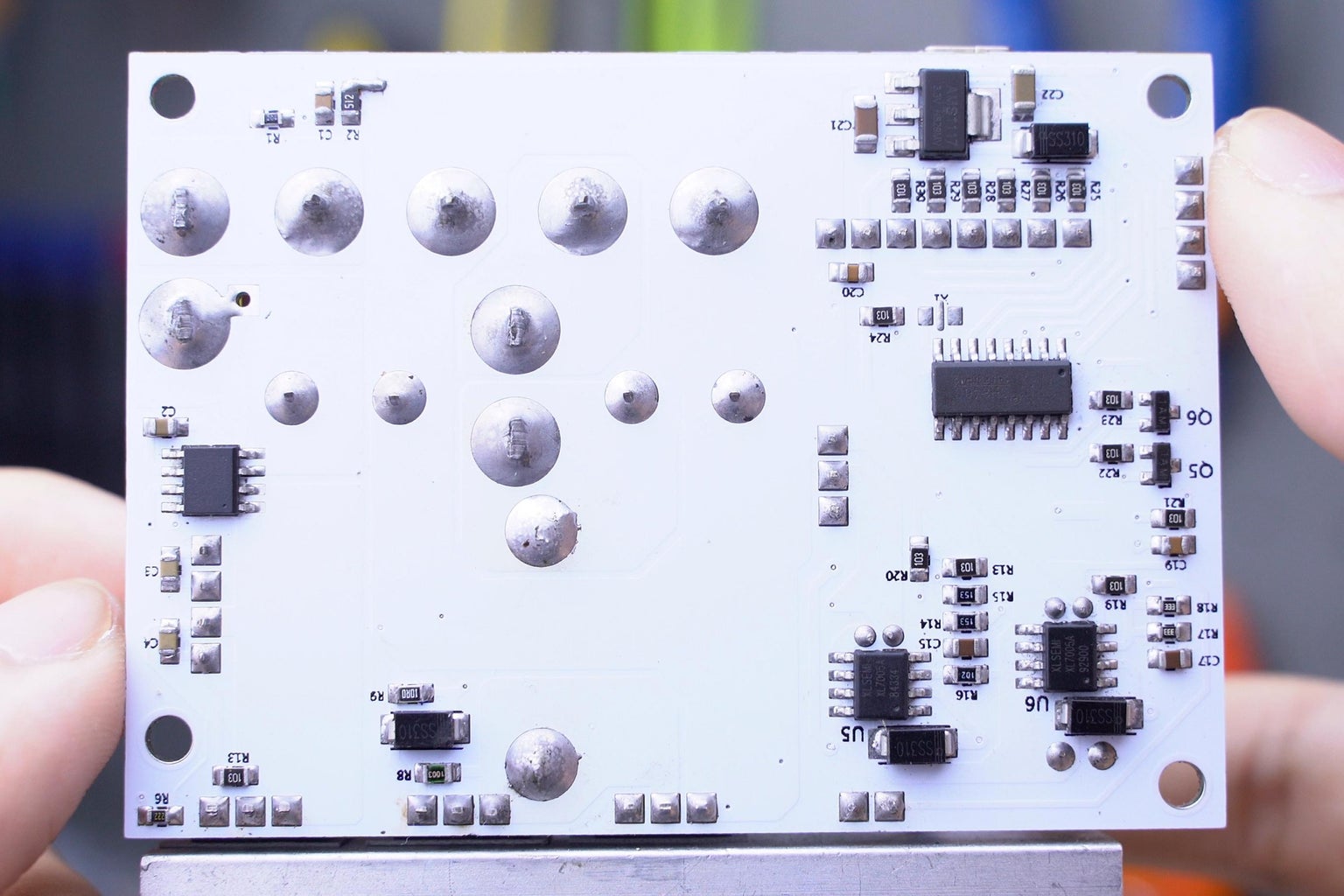
Step 13: The PCBs


You can purchase my fabricated boards from the PCBway links below. These are quick links, so you wouldn't have to upload gerber files to the website. If you are interested in the gerber. You can find it in the google drive file package link. You can buy 10 pieces of the board for $5 (be sure to input 10pcs. since 5pcs is set by default). I do appreciate it when you buy from my PCBway link, I use the commission to fund my other projects and tutorials, your support would be much appreciated.
PCBWAY PCB LINKS:
1.) Main MPPT Board (https://bit.ly/3gGccE7)
2.) Button Breakout Board (https://bit.ly/3kuwHF6)
3.) 2 Pin Fan Breakout Board (https://bit.ly/3jsmWIn)
GOOGLE DRIVE ALL FILES: (Schematics, PCB, Parts List, Firmware)
https://drive.google.com/drive/folders/1Sd2jWAb-F8...
I did my best to make an extremely compact board without butchering the line gaps and widths. I won't be providing printable PDFs for homebrew PCBs for this specific design since it uses a lot of vias and would be nearly impossible to make a homebrew PCB without using electroplating.
The project does involve a lot of surface mount components. This is my first tutorial to feature an SMD design. This isn't my first board to use SMD though, I started way back from 2017. I've made hundreds of boards that used SMD, but I don't feature it in my tutorials that much in fear that other enthusiast for fear of building it. For those who are new to SMD board projects, based from experience, it's actually easier to assemble than through hole designs (THT).
Step 14: Materials Needed


I buy parts in bulk, the individually priced total component cost of the MPPT project is around $20 in the Asian market. Prices may vary depending on where you buy your components from.
Complete Components List With Links: (click to view excel parts list)
Main Components:
- ESP32 WROOM32 MCU Module
- ADS1115/ADS1015 I2C ADC
- CSD19505 2.6mΩ N-ch MOSFETS (3x)
- ACS712-30A Current Sensor IC
- IR2104 MOSFET Driver
- B1212 DC-DC Isolated Converter
- XL7005A 80V 0.4A Buck Regulator (2x)
- CH340C USB TO UART IC
- 16X2 I2C Character LCD
- AMS1117-3.3 LDO Linear Regulator
- AMS1117-5.0 LDO Linear Regulator
- SS310 & M7 Diodes (refer to excel sheet)
- SMD Resistors & Caps (refer to excel sheet) - Inductor Core & MISC. (refer to excel sheet)
Tools Required:
- Soldering Iron
- Soldering Lead
- Tweezers
- Desoldering Pump
- Hot Air Reflow Station (optional)
- Solder Paste (optional)
PARTS SOURCE (PHILIPPINES): https://www.e-gizmo.net/oc/index.php
PARTS SOURCE (GLOBAL ALTERNATIVE): https://lcsc.com/
Step 15: Component Alternatives


If you are new to surface mount (SMD) you can buy module breakout boards like these. Use a pair of tweezers on the component you want to desolder than heat the pads with a hot air reflow gun. In some instances this is a cheaper way of getting the chips without buying in lots or bulks.
SMD resistors are labelled. For example a 10k ohm resistor is 103, a 2.2k resistor is 222... SMD capacitors on the other hand are not labeled. You have to use your multimeter's capacitance testing feature to know the capacitance of MSD capacitors when you are recycling them from boards.
Step 16: Board Assembly (Soldering Iron Method)


As seen on the video, there are various techniques you can use to solder the SMD components without using solder paste and a hot air reflow gun. This is how I soldered SMD components when I got into SMD back in 2017.
General Technique:
- Solder a single pad
- Grab you component with a tweezer
- Align it to the pads
- Melt the tinned pad that you have soldered previously. This acts as an anchor to your components
- Solder all the remaining feet of your components to the pads
- A little bit if flux on the surface helps with the soldering
- If the flux and solder creates a char or burnt residue, use a toothbrush and clean the board with alcohol
Step 17: Board Assembly (Hot Air Method)


My next favorite technique is the handheld reflow SMD soldering technique. What's my first? A PID oven if my first, but I won't be showing that today. Let's go with the easiest SMD soldering technique.
Handheld Soldering Reflow Technique:
- Grab a solder paste syringe
- Inject a blob of solder paste on your PCB's pads
- Align your component to the pads
- Heat the pads with a hot air reflow gun
- The paste would start to melt and the component's feet will magically align with the pads as the solder paste melts and becomes a solder joint.
- If your components misaligned with your pads, use a pair of tweezers to realign them while using a hot air gun to melt the solder again.
- That's it! Easy!
Step 18: The USB Port (Take Note)


Take note that the Mini USB port comes with nibble guides. These are meant to be used for proper alignment of the USB port to the board during automated factory assemblies. I did not implement holes to my PCB since I used the area underneath for line traces. For you to be able to solder this flat on the board and pads, you would have to snip of these nibbles.
Step 19: The CH340x UART Chip (Take Note)

If you are using the CH340C variant of the CH340 USB-TTL UART chip, kindly disregard the X1 pad by leaving it unpopulated. If you are using the CH340G, you must solder an SMD 12MHz crystal resonator on the pad, since the CH340G variant does not have an internal crystal built in to the chip. Bottom-line: get the CH340C it's priced the same and has the same specs.
Step 20: Proper Heatsink Installation (Isolation Required)


If you are new to TO-220 packaged transistors, kindly read this and pay particular attention. MOSFETs using the TO-220 package always have their "drain" pins tied to the MOSFET tab, yes they are electrically connected. Screwing the MOSFETs directly would cause the heatsink to conduct with all the drain pins of the MOSFETs.
Now let's do a recall from the schematic. MOSFETS Q1 and Q2 have drain pins that are connected in the first place, there's no need for isolation between the two MOSFETs. MOSFET Q3 on the other hand has a "drain" pin that should not be conducting with Q1 and Q2's drain pins. Q3 is the MOSFET we need to isolate from the heatsink.
Steps For Heatsink Assembly:
- Solder the MOSFETs first to the board.
- Grab you heatsink and place alongside with your MOSFETs
- Use a marker to mark the holes be drilled
- I am using 3.2mm bolts, so use a drill bit slightly smaller than the bolt size
- Drill through the aluminum heatsink.
- Before proceeding to the Isolation steps, force screw the bolts to the heatsink to create a thread on the heatsink. This is a simple, barbaric and effective way to have a thread or grooves on your heatsink without using tapping tools.
Steps For Isolation:
- Insert the plastic isolation bushing to your MOSFET's hole or sleeve it on your bolt instead.
- Add the fiberglass or Mica isolation pad between your MOSFETs and heatsink.
- Screw the bolt with the plastic insulation bushing in between the MOSFET and heatsink
If Q3 is the only MOSFET needed to be isolated from Q1 and Q2, why did you Isolate them all on the video?
I isolated them all because I didn't want the heatsink to be connected anywhere to the circuit. This was important to me especially during the time the board was under development and undergoing tests. If I leave Q1 and Q2 connected to the heatsink the heatsink would could conduct 80V from the panel, this was a risk I didn't want to take when I was probing through the different pins for my lab equipment tests. One slight touch from a stray wire could have potentially damage my build, that's a lot of parts to replace. On the other hand isolating Q3 only while leaving Q1 and Q2 conducting through the heatsink has a slight benefit, this provides a lower resistance path between Q1 and Q2, it it negligible though. I would recommend isolating them all from each other.
Step 21: The NTC Thermistor Temperature Sensor


NTC thermistors come in different packages. I bought the ring type of NTC thermistor since all I had to do with screw it on my heatsink. It is isolated so no need for galvanic isolation. If you go with the thermistor that looks like a capacitor, just glue it on the heatsink. The leads of the thermistor goes to R35 of the board. These things are non-polarized you can connect the two pins in both ways.
Step 22: Select a Fused Rated for Your Needs

You will notice I used 20A Green Mini Automotive Fuses and not the 35A I recommended from the schematic. The reason why I did this was to protect my circuit to what my solar setup runs with. While the MPPT runs with a ton of safety protection protocols, these protocols and safety features are microcontroller and code dependent. If the microcontroller were to malfunction and enter a lock-up state (which is highly unlikely based on my field test), the fuses could save a lot of your hardware from frying. I did not have the proper solderable fuse connectors at the time I documented this project, so I just soldered them to the board directly.
How To Select Fuses:
- F1 or Fuse1 needs to be rated for your input current (solar input). Your fuse1 rating must be close to your solar setup's combined Imp (maximum point current).
- F2 or Fuse2 needs to be rated for your output current (battery charging current). Your fuse2 rating must be close to your battery charging current. (Mine was 30A, but I limited it to 20A eventually to prolong my battery pack's life)
- You can still use 35A fuses and treat this unit as any commercial MPPTs would. This is by assuming that all fuse ratings are designed for maximum advertised operating conditions. Just be weary that using fuses that are far from your current setup's currents could prevent the fuses from doing there jobs in saving your MPPT from unexpected faults.
Step 23: Solder or Screw?


I made the solar and battery holes large enough for wires. You can solder wires directly if you plan to have the connectors mounted externally. I wanted to make mine screwable so I went with a 50A rated screw terminal for it. If you plan do the same and go with my 3D printed enclosure, kindly remove the screw terminal's cover.
Step 24: Solder the Remaining Components


If you have watched the video, I showed a specific sequence of which parts to solder first. This was because surface mount components are much more difficult to solder when the THT components are soldered first (tall THT components block areas beside SMD components).
Solder all the SMD components first and the THT follows.
Step 25: Designing the Inductor


If you plan to follow my exact general design, you can skip this step but if you plan to use a different inductor inductance from your design, or perhaps use a different toroidal core from the 0077071A7 core model I used, this step will guide you in designing the required toroidal core for this project.
The Inductor I Used:
- Model: 0077071A7
- Manufacturer: Magnetics Inc.
- Core Material: Kool Mμ (Sendust - FeSiAl)
- Relative Magnetic Permeability: 60μ
- Dimensions: OD = 33.5mm , ID = 19.5mm, H = 11mm
- Al = 61 nH/T^2
- Ae = 65.6mm^2
- Bsat = 1.0T
- Individual Price: $0.50 USD (25 PHP)
- Retail Supplier Link: Click Me
- Datasheet Link: Click Me
Steps In Building A Toroidal Inductor:
- Find a suitable toroidal core (T-130 or larger)
- Yellow #26 iron powder core material is a common choice for the toroidal cores used in buck regs (you can go with these). Although I went with a sendust (Kool Mμ by Magnetics Inc.) since it is known to have 40-50% lesser core losses than of the regular Iron powder core material.
- Visit Coil32's online calculator (Click me)
- Scroll down and find ferrite toroid calculator.
- We will be using a gauge 16 magnet wire, there is a dropbox on the upper right and select "AWG 16"
- In the text box "L", input the inductance that you would want your inductor to have. My MPPT design required an inductance of 64μH, so I entered 64 in the box. (it was actually 48μH, the previous steps discussed why it became 64μH).
- OD refers to your toroid's outer diameter, measure yours in mm and input it in the text box.
- ID refers to your toroid's inner diameter, measure yours in mm and input it in the text box.
- H refers to your toroid's height or thickness, measure yours in mm and input it in the text box.
- You can leave Chamfer to 0mm, unless your toroidal core's datasheet specifies it.
- μr refers to the "Relative Magnetic Permeability". This one is tricky and is often found in in your toroidal core's datasheet. Luckily 0077071A7 has a datasheet that specified it of having 60μ, so I entered 60 in the text box. If you are dealing with an unknown toroidal core with no label, observe if it was colored with paint, some toroidal inductors have colors to specify the core material. Yellow toroids are often 75μ. (inductor color code article)
- Do not touch the other text boxes, leave them be!
- Press the "Compute" button.
- You will get results down below
- N - is the number of turns of gauge 16 magnet wire that you would have to wind around the toroidal core in order to get the inductance that you have specified in L
- Lw - is simple an approximation on the length of wire that you will need in order to get N number of turns around the toroidal inductor.
The Inductor Current Rating
The inductor current rating that you would often find in prebuilt inductors refer to something called the inductor saturation current. This refers to the applied DC current at which the inductance value drops a specified amount below its measured value with no DC current. Some manufacturers will rate their parts for a 30 % drop in inductance. Remember that inductors are really fast energy storage devices. Energy is stored through a magnetic field generated by the current flowing through the inductor. Materials can only store a specific amount of energy an inductor can take in. When an inductor can no longer absorb energy, the inductor saturates as the inductance decreases as well. Building an inductor and getting the required number of turns to get the required inductance is easy! But determining the inductor current from your toroidal inductor design is something that has haunted me for months! It is also not something you can easily come across google! There are two ways to determine the inductor current; one is by using datasheets and formulas, and the other is by conducting a inductor pulse test with an oscilloscope connected to a homebrew rig (which I will be demonstrating later).
Formula/ Calculator Method:
- Visit Pigeon's Nest Calculator (Click me)
- If you want to learn, you can find the formulas from there as well!
- You will be asked to fill some parameters.
- These parameters can only be found from your toroidal core's datasheet
- This is why I said it was difficult. Very few manufactures specify these fields in their datasheet.
- The parameters Al is the inductance per turn. This is something you would find in a toroidal core datasheet. If you don't have datasheets for your toroidal core, you can visit (this link) for finding Al values for generic iron powder core toroids.
- Ae is simply the effective cross-sectional area of a toroid. This can also be found in the datasheet. If you don't have one, use a formula from your geometry subject to solve for a toroid's cross-sectional area.
- L is simply the inductance that your designed inductor has.
- Bsat is the Magnetic Saturation Flux Density and it is one of the most difficult to find. I couldn't even find it in the datasheet, I didn't want to settle with Pigeon's Nest's 0.4T assumption since I'm dealing with a different core material. Luckily, I found (this article) showing the different magnetic flux densities (Bsat) of the common core materials used in toroids. (Sendust Kool Mu cores like mine turned out to have a Bsat = 1.0T). But, if you are dealing with a generic iron powder core, Bsats can be found from (visit this link).
- Now that we have everything we need. Press the "Calculate" button on the Isat box.
- Isat is now your Inductor's Saturation Current Rating!
Articles You May Want To Read:
Step 26: Build the Inductor


Are you using the 0077071A7 toroidal core? Follow my lead!
Steps On Building The Inductor:
- Grab a tape measure and cut 1.3 meters of Gauge #16 magnet wire.
- Wind it around the toroidal core 30 times. Clockwise or counterclockwise, it doesn't matter.
- There will be a slight excess of wire after 30 turns. Cut the excess off but leave some behind for the inductor's feet.
- The magnet wires at the ends must be sanded or filed! Magnet wire are enamel insulated. You have to scratch that enamel layer off to be able to solder the inductor to the PCB.
- You now have a 64uH 33A inductor! Some powerful stuff we got here!
Step 27: Testing the Inductor's Inductance (Optional)


It is a good practice to verify a newly built inductor's inductance. Getting the wrong inductance from your initial design is possible, especially if some of you are relying on generic toroidal cores. I was confident with mine since I built it on a branded toroidal core that came with a datasheet. Nonetheless I ran an inductance test. I used my Agilent 4263B Lab Grade LCR meter to verify mine. After connecting my inductor to the LCR meter's kelvin probes the LCR meter displayed 63.790uH! That's really close to my 64uH goal, it was perfect!
You don't need fancy equipment like the Agilent LCR meter. You can grab yourself a $7 LCR meter for checking your inductor inductances. The cheapo LCR meter measured 0.05mH (50uH). It was poor in resolution, but hey at least you get a good estimate if your DIY inductor was close to your target inductance. Just don't expect it to be as precise and accurate as lab grade LCR meters.
Step 28: Testing the Inductor's Saturation Current (Optional)


Now we can verify the inductor's saturation current. As mentioned from the previous step, the inductor's saturation current is one of the factors that dictate on how much current our MPPT can handle. So I needed to be sure if my newly built inductor can truly handle 33A from what I have computed. So I built this inductor test rig that works with an oscilloscope. We have a large low ESR capacitor bank for storing energy, a MOSFET to switching the circuit, a 0.1 ohm shunt resistor for current sensing, Arduino ESP32 MCU for sending pulses to signal the MOSFET and a rotary encoder to set the MCU's pulse duration.
The periodic frequency of the inductor test rig I built is 20Hz, it is design to be slow in order for the capacitor bank to charge. The on state of the pulse duration can be set from 1 nanosecond to 30 milliseconds. By adding a BNC connector to my oscilloscope and connecting that BNC connector across the shunt resistor, we can measure the voltage across the shunt resistor to measure the current. The curve you are seeing on the oscilloscope's display is the current flowing across the inductor.
As expected, the inductor has a soft saturation current. This is common for powder core inductor materials. The saturation current point can be found at the point when the current ends to behave linearly (found at the end of the straight line). It is difficult to tell, but it is around 1.8 divs from the zero point to the saturation point. By using ohms law, the voltage measured across the shunt resistor and the resistance of the shunt resistor, we can get Isat or the saturation current.
- Isat = Vshunt / Rshunt
- Isat = (1.8divs * 2V/div) / 0.1Ω
- Isat = 36A
- We have a 36A inductor!
It turns out we have a 36A rated inductor, that is 3A higher than the 33A inductor design that we have predicted. Our MPPT would be able to handle 36A after all!
Step 29: Solder the Inductor and the Bulk Capacitors


Once you have finished mounting the MOSFETs and building the inductor, you can now solder the inductor and bulk capacitors to the PCB.
Step 30: 3D Printed Enclosure


I am providing two 3D printed downloadable enclosure designs to choose from. You have a slim enclosure for a strip down WiFi only build and a full-sized enclosure built for the WiFi MPPT with a 16x2 LCD and four navigation buttons.
3D Printing STL File Download:Click Me
Step 31: Adding a Cooling Fan (2-Pin Fan Breakout Board)


You can omit using a cooling fan if you chose opt to use a larger heatsink. The original MPPT board design was meant to work with 3-pin PWM cooling fans. If you plan to use a 2-pin 12V cooling fan, a breakout board adapter must be built for the MPPT to properly work with a 2 pin cooling fan. Take note the if you were to substitute a MOSFET from the schematic shown above, be sure to select a logic level MOSFET such as the IRLZ44.
Step 32: Mount the Main MPPT Board to the Enclosure


Mount and secure the main MPPT board on the enclosure with screws. The 3D printed enclosure comes with printed standoffs, no need to buy those brass standoffs o keep the board elevated from the enclosure's floor.
Step 33: Adding the Buttons & LCD


I used the cheapest LCD I could find since I am going to use the WiFi phone app much more often in the first place. For the LCD I have chosen an Arduino compatible 16x2 character LCD with an I2C backpack driver. I also built a simple breakout board for the tact buttons which also acts as an I2C port expander. I forgot to send the design over to PCBway so I made a quick homebrew breakout board.
Connect the four LCD wires to one of the button breakout board's I2C expansion ports. Then, connect 8 wires from the button breakout board to the main MPPT board's interface port.
Step 34: Front Panel Assembly


The 3D printed enclosure also comes with 3D printed button caps. You may add some tape for extra padding between the buttons and tact switches to eliminate the plastic rattling sound. Use your tweezers and insert the button caps to the front panel's back and screw the button breakout board and LCD in place.
Step 35: Final Assembly


You can now screw and close the enclosure. I also screwed a pair of gauge 12 wires to the solar and battery ports then soldered some detachable XT60 connectors and the ends of each pair for convenience.
Step 36: Connect to USB & PSU


Connect a Mini USB cable from your MPPT to your computer's USB port and provide power at either the solar or battery port of the MPPT using any power source. The MPPT can still be programmed even without being powered externally but the LCD would be unreadable unless powered externally.
Step 37: Programming the Arduino ESP32 MPPT


The MPPT project is Arduino based. You can treat it just like any other Arduino ESP32 development board. I wrote a general purpose firmware code for all my future MPPT builds, I call it the Fugu Firmware. There are thousands of code lines, these codes are subdivided into 9 different sketch tabs for organization. You don't have to change anything! The only thing you need to add is your WiFi SSID, WiFi password and Blynk authentication token if you want the WiFi phone app telemetry to work. The rest can be set through the LCD interface. Your priority is just to be able to upload these Arduino Sketches (Fugu Firmware) to your MPPT.
ATTENTION:
- This code has been tested on the ADS1015. If you are using an ADS1115 kindly read the ADC selection step below
STEPS:
1.) Install The Latest Arduino IDE:
- Link for the latest Arduino IDE software
- The project is an Arduino based ESP32, you will have to download the Arduino IDE in order to upload the firmware or program to the ESP32 MCU.
2.) Download The Fugu MPPT Firmware:
- Download the latest version from GitHub (V1.1 & above)
- Download the initial release from gDrive (V1.0)
- The GitHub link will provide the future updates for the Fugu firmware
- The google drive link includes the initial stable release featured in the tutorial
- There are currently nine .ino files for the firmware, you would have to place them all in one folder. Name the main folder after the main .ino file (folder name example: ARDUINO_MPPT_FIRMWARE_V1.1). If you fail to do this, the Arduino sketch/ firmware would not open properly.
- Click on any of the sketches with the properly labeled folder to open the program.
- If you see all the .ino tabs upon opening the Arduino IDE, that means you have opened the code properly.
- I used the Arduino tab feature to subdivide thousands of code lines for organization. You can click on the tabs to view the different sections of the firmware.
- You can leave all the parameter initializations to it's default value as these can be set through the LCD interface of the MPPT later.
- My code's comments will guide you in understanding the codes in case you want to learn how the firmware works.
3.) Arduino Libraries Required To Be Installed:
- Blynk ESP32 Library
- Liquid Crystal I2C LCD Library (By: Robojax)
- Adafruit ADS1x15 Library
- The rest of the libraries come with the Arduino IDE by default
- The code/ firmware would not work compile these libraries
- If you are new to Arduino libraries, kindly search "how to install Arduino libraries"
If you have trouble finding these libraries, you can just copy my personal Arduino library folder and paste it to your IDE! (My personal Arduino Library Folder Link)
4.) Add WiFi IoT Credentials To The Code:
- Plan to use the MPPT WiFi telemetry phone app? Follow these steps!
- In order for the MPPT's ESP32 to connect to you WiFi router, you would have to input your WiFi credentials
- Find ssid[] = " ", then input your WiFi SSID in the " "
- Find pass[] = " ", then input your WiFi password in the " "
- The blynk phone app has a privacy and security feature. Blynk (Legacy) sends a unique authentication token to all users upon registration. This token is unique from all other tokens and ensure that only you, have complete control and access to your project.
- Copy the Authentication token sent by Blynk from your email.
- Find auth[] = " ", in the code and paste your token in the " "
5.) Selecting The Proper ADC Library For The ADS1015/ ADS1115
- The ADS1015 and ADS1115 ADCs are cross-compatible. But you have to specify which chip model you are using in the code.
- If you are using the ADS1015, leave everything by default! Do not change anything!!!!!!
- If you are using the ADS1115 kindly follow these steps:
- Delete the line "Adafruit_ADS1015 ads;"
- Uncomment "//Adafruit_ADS1115 ads;" by removing the "//" from the beginning of the line.
6.) Electrical Price Setup
- The Blynk MPPT app can keep track of how much money you have saved from harvesting energy in kWh.
- To setup your energy savings currency you have to specify your local electrical currency rate (ex: 0.5 USD/ kWh)
- It is found in the main sketch of the code, under the USER PARAMETERS section
- Change the value in "electricalPrice = 9.5000;" to whatever your electrical price costs in your country. Example, 1kWh in our country costs 9.5 PHP. So input 9.5000 to the "electricalPrice = ;"
7.) Arduino Tool Settings:
- Hover over the tools tab
- Just follow the settings I use for uploading sketches to the ESP32
- Board: ESP32 Dev Module
- Upload Speed: 921600
- CPU Frequency: 240Mhz (WiFi/BT)
- Flash Frequency: 80MHz
- Flash Mode: QIO
- Flash Size: 4MB(32Mb)
- Partition Scheme: Default 4MB with spiffs (1.2MB APP/1.5MB SPIFFS)
- Core Debug Level: None
- PSRAM: Disabled
- Port: Select your com port
- Programmer: AVRISP mkII
8.) Upload The Codes/ Firmware
- On the upper right of your Arduino IDE, click on the check icon to compile.
- Wait for a few seconds for the program to compile.
- If your program compiles without errors, this means you are ready to upload the program.
- Click on the Right Arrow button to upload the program to your MPPT's Arduino ESP32.
- It will say done uploading once all the codes and sketches successfully upload.
- Congratulations! You now have a firmware for your MPPT project!
CALIBRATION
- Current sensor calibration is not required as the Fugu MPPT firmware comes with automatic current sensor calibration
- Temperature sensor calibration can be done by changing "ntcResistance = 9000.00". This is the NTC resistor's rated resistance value. I am using a 9k ohm NTC which explains the 9000.00.
- Voltage calibration on the other hand can be done by trial and error. Follow these steps:
- Enter the settings menu an leave it open every trial. Entering the settings menu puts all charging processes to a halt. You have to do this every time you upload the code to the MPPT since the MPPT will reset back to the Main Menu every time you upload the code.
- Connect the MPPT's solar panel input to a PSU (set it to 60V)
- Connect the MPPT's battery output to a battery pack
- Connect the MPPT to a USB port
- Open the Arduino IDE on your PC
- Press CTRL+SHIFT+M to open the serial monitor
- Find VI in the serial feed.
- Measure the voltage at your input using a voltmeter
- If your serial feed reads a higher or lower voltage from your voltmeter's measurement calibration needs to be done to the input voltage sensor.
- Find the "inVoltageDivRatio = 40.2156" from the calibration parameters section of the main code. Increase or decrease it
- Upload the code to the MPPT
- Measure the input voltage again with a voltmeter and compare the serial feed's measured VI. Do this step again and again until your voltmeter measures the same voltage as your serial feed's VI
- The same thing applied to the output voltage sensor. Do these exact same steps for "outVoltageDivRatio = 24.5000"
- inVoltageDivRatio and outVoltageDivRatio are pre-calculated voltage divider ratio values for the input and output voltage dividers. Writing the resistor values individually takes up processing power, this was done to reduce processing time. The formula is the inverse of the voltage divider formula:
- "Voltage Divider Ratio = ((top resistor + bottom resistor) / bottom resistor)"
- I hope this explains why you guys aren't seeing resistor values in the code.
ADDITIONAL NOTES:
- These notes are for those who plan to modify the firmware. If you just want to use the MPPT unit as intended, you may skip reading this notes section.
- ADS1015 and ADS1115 are both compatible on the same code, the library works for both! Please don't change anything!
- The LCD menu interface uses the non-volatile flash memory to save all your settings. These settings are pre-loaded upon startup. If you plan to use the MPPT without the LCD and buttons, you can override the autoload feature by changing the disableFlashAutoLoad = 0 to disableFlashAutoLoad = 1. This will disable the MPPT from grabbing the saved settings from the LCD interface and use the default settings at the Arduino sketch. You can manually set the battery voltages, currents & etc... through the parameter section of the code. From here you can also access a lot of hidden features that you can't find from the LCD interface.
- Disabling the WiFi saves you 0.3-0.5W of power consumption.
- serialTelemMode gives you different serial feed formats.
- pwmResolution and pwmFrequency can be set to a custom switching frequency for the buck and PWM resolution (there is a limit to this, I made a step explaining the formula for the limit).
- avgCountVS and avgCountCS are number of voltage and currents sampled from the sensors for averaging. Setting these both to 1 would disable sampling and will significantly make your code run faster and have faster tracking. I recommend 2 and 4, increasing the sampling count gives a cleaner sensor data at the expense of adding some processing time.
- There's a lot more! I need to make a separate tutorial for this (Part 3 of the Video
Step 38: MOD#1 UPDATE: Support for Batteries Up to 80V

I have received requests for battery support above 80V (12V/ 24V/ 36V/ 48V/ 60V/ 72V/ 80V). Follow these steps if you want to charge battery voltages from 0-80V.
1.) CHANGING THE VOLTAGE DIVIDER RESISTORS
- Change R32 to 200k Ohms
- Change R34 to 5.1k Ohms
- Leave R33 unconnected or unpopulated
2.) MODIFY THE CODE (ADJUSTING PARAMETERS)
- You have to change the set parameter values in the main sketch in the calibration parameters section
- Change "outVoltageDivRatio = 24.5000" to "outVoltageDivRatio = 40.2156"
- Change "vOutSystemMax = 50.0000" to "vOutSystemMax = 80.0000"
DISCLAIMER:
- There is no issue if you are using a legitimate ADS1115 16-bit ADC. But if you are using an ADS1015 12-bit ADC, voltage sensing resolution at the output will decrease as mentioned from the previous steps. I highly discourage modifying an ADS1015 system. Please do not attempt this mod if you do not know what you are doing! I am not liable to accidents that may result from attempting this mod.
Step 39: MOD#2 UPDATE: Support for Higher Solar Panel Voltages (100V-150V)

This V1.0 build can actually support solar panel voltages above 80V. Take note that this mod is also highly discouraged as it was not considered in the initial design process. Doing this mod will disable the PSU mode, you can no longer use the MPPT in bench bench power supply mode. I will not be giving the modified input resistor values and suggested MOSFETs for this mod. This is a test if you truly know how to get this mod done properly. But for those enthusiasts and engineers equipped with knowledge and experience, I will be giving some hints and tips on this step. Only attempt this if you know what you are doing! I repeat, I am not liable for any accidents caused by attempting this mod!!!
1.) SELECTING THE PROPER VOLTAGE DIVIDER RATIO
- Since we are dealing with a mod that increases the MPPT's input voltage. You need to properly select the proper voltage divider resistors to create a ratio for the 2.048V ADC voltage reference to properly scale and take your newly set input voltage scale into account.
2.) LETTING THE XL7005A HANDLE VOLTAGES ABOVE 80V
- The XL7005A can only handle 80V max! It can't handle anything above this! For this mod to work, you have to remove D8 to prevent the MPPT's system from drawing voltages from the input source which is your solar panel.
- Removing D8 while leaving D4 results to the MPPT drawing power only from the batteries.
- At this point, you probably know why I discourage this mod. If your synchronous buck malfunctions in terms of voltage regulation, it could potentially output voltages above 80V. A single short spike of voltage above 80V could damage the XL7005A buck reg chips instantly.
3.) MODIFY THE CODE (ADJUSTING PARAMETERS)
- Just like from MOD#1, you have to specify the changed voltage divider ratio in the code.
4.) SELECTING MOSFETS THAT CAN HANDLE IT
- Your MOSFETS needs to be replaced with ones that can handle your maximum input voltage. This is denoted by Vds in the datasheet. If you were to design a 150V MPPT, you have to find MOSFETs with a Vds slightly above 150V!
- Id and Rds(on) also needs to be taken into account
5.) CHANGING THE INPUT CAPACITOR (C7)
- There is one capacitor in particular that needs to be changed! C7! It needs to be rated slightly above you new input source voltage. If your mod will have a 150V input, C7 must be slightly above 150V as well, other wise it will explode!
Step 40: USB Serial Telemetry


The project also comes with a USB serial telemetry feed! You have the option to enable or disable this through the code. This feature can be used for diagnostics, troubleshooting, design tweaking, code optimization or perhaps experimentation on creating your own MPPT algorithm. This can be accessed through the Arduino IDE by pressing "CTRL+SHIFT+M" to display the serial monitor.
Variables In USB Telemetry Feed
- ERR - Number of errors present
- FLV - Fatally low system voltage (unable to resume operation)
- BNC - Battery not connected indicator
- IUV - Input undervoltage indicator
- IOV - Input overvoltage indicator
- OOV - Output overvoltage indicator
- OOC - Output overcurrent indicator
- OTE - Overtemperature indicator
- REC - Recovery from fault indicator
- MPPTA - MPPT algorithm enable indicator
- CM - Output mode (1 = Charger mode, 0 = PSU mode)
- BYP - Backflow Current Control Unit MOSFET indicator
- EN - Buck Enable Indicator (1 = MPPT Buck is Operational, 0 = Not operational)
- FAN - Fan Running Indicator
- WiFi - WiFi Enable Indicator
- PI - Input Power (Power harvested from solar in watts)
- PWM - PWM injected to the IR2104 (decimal equivalent value)
- PPWM - Allowable PWM Floor Limit
- VI - Input Voltage (solar panel voltage in volts)
- VO - Output Voltage (battery voltage in volts)
- CI - Input current (solar panel current in amps)
- CO - Output current (battery charging current in amps)
- Wh - Energy harvested (in watt-hours)
- Temp - Heatsink Temperature (in degrees Celsius)
- CSMPV - Calibrated current sensor zero current point
- CSV - Instantenous current sensor analog voltage output
- VO%Dev - Percent deviation of VO from the set maximum output battery voltage (in %)
- SOC - State of charge, the battery's charge (in %)
- LoopT - Loop time, the time it takes to complete one loop cycle of code (in miliseconds)
Notes
- For boolean vars like FLV to EN; 1 means true and 0 mean false.
Step 41: WiFi Telemetry App


The project has a WiFi telemetry and free sever based datalogging phone app. The MPPT's phone app is based on the Blynk Legacy platform. It is available from to both Android and IoS.
Steps In Installing The Phone App:
- Download it from the app store and register as a new user.
- Open the QR code scanner in the Blynk Legacy App
- Scan the QR code from the image above
- You instantly get a copy of the MPPT's phone app!
- Just click the play button for it to start
- You can add a home menu shortcut so you can open the MPPT app directly without going through the blink menu all the time.
Features Of The MPPT Blynk App:
- Displays a live feed of the energy harvested from the Solar Panels
- Displays solar panel Power (watts)
- Displays solar panel Voltages and Currents.
- Displays battery charge in %
- Displays battery's charging Voltage and Current
- Displays energy harvested in kWh
- Displays energy saved in currency (USD, Euro, Peso & etc...)
- Displays temps
- Three different real-time graphs of all the displayed data.
- The data is logged at Blynk's free database and refreshes every year.
Watch The Blynk Tutorial (Skip To: 13:01)
Step 42: Setting Up the MPPT (via LCD Menu)


Just like any other off the shelf commercial MPPT, I have added an LCD interface to project. This is not only used data for display but for also setting up the MPPT's settings without dealing with codes. The interface is dead simple and easy to navigate through. Here is the LCD Menu's layout:
Navigation Buttons (1, 2, 3, 4):
- Left Button
- Right Button
- Back Button
- Select Button
MAIN PAGE #1
- Row 1: Solar Power, Energy Harvested, Days Running
- Row 2: Battery %, Battery Voltage, Battery Charging Current
MAIN PAGE #2
- Row 1: Solar Power, Solar Voltage, Solar Current
- Row 2: Battery %, Battery Voltage, Battery Charging Current
MAIN PAGE #3
- Row 1: Solar Power, Energy Harvested, Battery %
- Row 2: Energy bar with 16 blocks representing battery life 0-100%
MAIN PAGE #4
- Row 1: Temperature Stat label
- Row 2: MPPT Temperature, Fan Status
Main Page #5 (Settings Menu Prompt)
- Press select to enter the settings menu
- Entering the settings menu puts charging process to a halt for safety.
SETTINGS MENU
- Supply Algorithm
- MPPT + CC-CV - use this if you you are using solar panels or wind turbines for your MPPT's input. The MPPT algorithm is required to extract the most power out of your solar panels and wind turbines.
- CC-CV Only - use this if you plan to connect your MPPT's input to a PSU.
- Charger/ PSU Mode
- Charger Mode - ALWAYS USE THIS WHEN CHARGING BATTERIES! When charging batteries, the Charge Mode needs to be selected as it contains all the safety protocols required for battery charger. This includes the battery disconnect and connect feature! Without this, your MPPT will definitely get damaged upon connecting to a battery.
- PSU Mode - you can use this if you plan to connect the MPPT's battery terminals directly to a DC load such as an inverter without using batteries. Yes the MPPT can operate without batteries. This is an experimental feature that can be useful for tinkerers. You can also use the MPPT unit as a programmable buck converter or bench power supply.
- Max Battery V
- Input the maximum charging voltage your battery pack can handle
- Selectable from 0-50V
- Min Battery V
- Input the minimum battery voltage your battery pack has
- Selectable from 0-50V
- This is important for the state of charge
- Charging Current
- Input the charging current that your batteries can handle\
- Selectable from 0-50A (please don't exceed 35A for this unit)
- Fan Enable
- Enable - The cooling fan will operate when the fan temperature is reached
- Disable - Forces the cooling fan to turn off 24/7.
- Fan Temperature
- The temperature at which the cooling fan will turn on
- Selectable from 0-120 deg C (default is 60 deg C)
- Shutdown Temperature
- The temperature at which the MPPT will stop charging to prevent overheating
- Selectable from 0-120 deg C (default is 90 deg C)
- WiFi Feature
- Enable - Turns on WiFi feature (consumes 0.3W of power)
- Disable - Turns off WiFi feature for power saving.
- Autoload Feature
- Enable - Autoloads stored settings from the flash memory upon startup
- Disable - Disables autoload and uses Arduino default variable settings instead.
- Backlight Sleep
- Turns off backlight when no buttons are pressed for a settable duration
- Durations: Never, Seconds, Minutes, Days, Weeks and Months
- Factory Reset
- Resets all the MPPT settings back to default
- Press select then select yes to reset
- Firmware Version Page
- Displays the Fugu MPPT Firmware version that is installed on the unit.
Step 43: Setting Up My Solar Panels


I have two 320W solar panels connected in series. Philippines is still in lockdown due to the pandemic. We don't have the manpower to install these solar panels on the roof so I went with a temporary solution. I laid a lengthy flat cord wire (guage #14) from our yard to my workspace. I am aware of the losses that this solution incurs. That is why I went with series, to increase the voltage and decrease the current, reducing the losses compared to using a parallel setup.
Step 44: My Workspace Off-Grid Setup


Here's a photo of my MPPT's first day of installation from 6 months ago. I am still using it up to this date and has remained problem free from the past 6 months and counting. It has harvested over 334kWh of energy from my solar setup since it was first installed. It isn't much since I don't consume much power in the workspace. It is connected to my 1kVA 220V pure sinewave inverter and to my 8S 2.56kWh LiFePO4 Battery Pack (it's now in a fireproof box).
Step 45: 98% Peak Efficiency


If you have watched the video, you will find the different board revisions I made. I made a homebrew PCB version of my final build, which is a stripped down version of it (running on a single ESP32 core, WiFi disabled & no LCD).
From the stripped down version, I did an efficiency curve test by connecting voltmeters and ammeters at the MPPT's input and output ports. I then connected a variable load controller with a nichrome water bath as a high power load. As I increased the load, I recorded the corresponding voltages and currents to compute for the power-in and power-out per row. After using the efficiency formula, I plotted the points on a graph to find the efficiency curve.
To my surprise it recorded a conversion efficiency rating of 98.6% at 270W with an input of 61.4V and an output of 27.00V. I was unable to find the end of the graph as my pocket DMM's ammeters were limited to 10A. It sounded to good to be true and I remain skeptical to whether my 9999 count pocket DMMs are accurate enough. On the bright side, even without active cooling the MOSFETs barely heated up, it's a good sign that we have minimal conduction losses from the MOSFETs. Part 4 of the video will be allotted for tests like these. I would have to revisit this and do it with my Agilent 34401A & TTi 1604 Lab DMM for better accuracy.
Efficiency Curve Lab Test Excel Sheet:
Step 46: Future Plans


I will keep you guys posted for updates. I hope you guys like this tutorial!
POSSIBLE MODS:
- You can actually modify this for 150V DC operation. It's simple, change the MOSFETs with a Vds of 150V, change the input voltage divider to a proper ratio for the input to be able to detect up to 120V/150V and finally remove D8 so that the MPPT's can just get power from the batteries and not exceed the buck regs' 80V limit. Part 4 of the video will explain this.
- The MPPT can actually charge battery chemistries up to 80V and not 50V! This was set in my original design, but I changed the output's voltage divider to a lower scale to increase voltage sensing resolution at the output. Changing the voltage divider resistors at the output with the same resistor values of the input, you can charge batteries up to 80V. You just have to change the voltage divider ratio value from the code as well.
- You can use a 20x4 character LCD or an I2C AMOLED LCD for better display. I didn't bother since I view most of the data from the WiFi phone app in the first place.
- Inductor can be mounted externally if you plan to build a bigger one!
- Connecting 4 MOSFETs in parallel to decrease on-resistance for lower conduction losses. This makes a higher current MPPT variant possible! A larger inductor is also needed to achieve this as well.
UPDATES:
- My plan for version 2.0 would be to use IGBTs to accommodate 150V or 300V solar panel setups and try to give it a 50A or 100A current capability. There is something called an interleaving synchronous buck configuration, this could easily increase the power handling capability of the MPPT.
- Coulomb counting for state of charge calculation is in the testing stage of my personal Fugu MPPT firmware.
- Part 2 of the video will show the complete design process of the MPPT
- Part 3 of the video will be the in-depth explanation of the Fugu MPPT firmware and the algorithms involved
- Part 4 of the video will be a montage episode of the tests that we will be conducting on the MPPT unit.


