

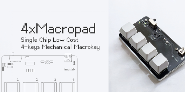
Introduction: DIY $3 Single Chip Macro Keypad From Scratch (Arduino IDE Programmable!)


Why $3 Macropad?
I have always been a great fans of Maker Faires around Asia and I am thinking if I could make something special so during maker events, I can exchange gifts with the makers I like so as to start a conversation with them. As a maker primarily working in the software and electronics fields, I really like the idea of PCB business card. However, most of the PCB business card ideas have already been done. From business card that play musics, light or mini game to the magical "My business card run linux" project. I want to come up with a new idea where no one have done before, yet cheap enough so I can afford to build a few of them and giving them out for free.
That is why I designed the "4xMacropad" - The business card size 4 key mechanical macropad. (Technically speaking the dimension is all "business card size" except the height)
Is it hard to make?
No. I strongly recommend this as your first "Tech Maker" project. This project contains the most basic elements of what a tech maker would usually use: PCB with SMT components, 3D printing and programming. There are a few advantage of this project as your first tech maker project
- All components are hand solder-able, the smallest footprint is SOP, which is relatively easy packet in SMT world (compare to SSOP, QFN or even BGA)
- Short working time: I can finish a board within 30 minutes :)
- Low Cost: The material cost are just $3 (without shipping). This comfort many beginner who are afraid of breaking expensive ICs or parts.
- Easy to program: I have already written a code generator / examples for you. You can pick up easily with little to no Arduino programming experience
So even if you are not used to working with SMT or programming, I still recommend you to give it a try :)
Lets get started!
Supplies

- Custom PCB
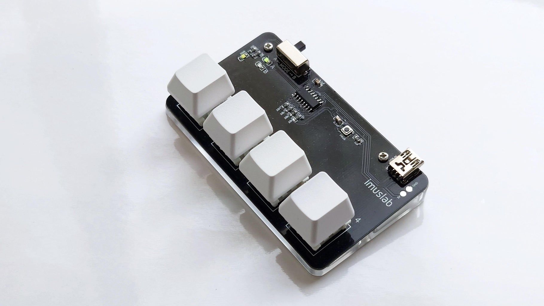
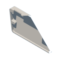
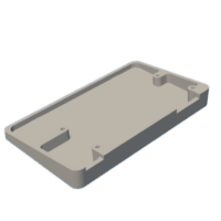
- 3D Printed base (for mounting the PCB at a tilted angle)
- 4 M2 x 5 screws
- CH552G E8051 Arduino IDE programmable MCU
- Mode switch
- SMT button
- Mini USB port
- 7 x 0805 10k Ohm SMT resistors
- 2 x 0805 0.1uF SMT capacitor
- 3 x LEDs (Power, Mode A and Mode B)
- 4 x mechanical key switches
- 4 x key caps of your preference
- Soldering tools
- Steady hand
Step 1: Print the PCB and Mount

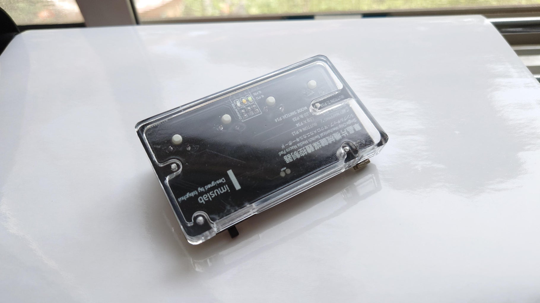
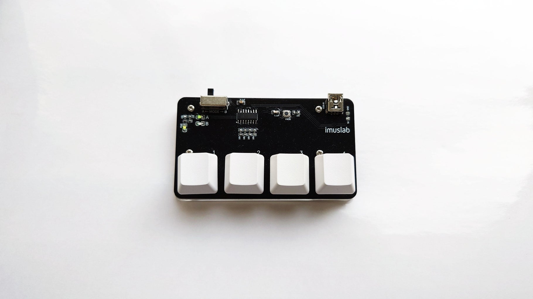
The most important part of this project is the PCB. The macro-keypad is designed with a open PCB design, which means the PCB is directly exposed on top of the device, making it a bit scifi style to look at.
As Instructable do not allow attaching zip file for gerber, I am putting it on Github where you can get it here.
Gerber File: https://github.com/tobychui/4xMacropad/blob/main/pcb/macrokeypad%20v3.zip
For the 3D Model file, you can edit it with Autodesk Inventor. They provide a free version for students where you can freely adjust the model based on your need.
In order to print my PCB, I place my order at PCBWay as they offer both glossy PCB and transparent 3D printing services, which make the exposed PCB looks even cooler!
Step 2: Solder the Components


For starters, I recommend starting from the smallest to the largest components. You can solder starting from the CH552G, then the surrounding 0805 ICs then the other remaining DIP type parts. Follow the silk screen instruction and solder everything in its correct locations.
There are also 3 optional RGB channel which they can be controlled by advance coding in the MCU. If you want to make some light pollution with those LEDs, you can also solder some extra 10k resistors and 0805 LEDs according to the silkscreen printing.
Step 3: Power Test

Before you plug it into your computer, you should do a power test using a lab bench power supply to the labeled 5V and GND test pad on the PCB. This is important to make sure there are nothing is shorted during the soldering process and the PCB is safe to plug into your computer.
Once powered on in, without any code in the MCU, you should be able to see the LED lights up in 50% brightness. That is because the LED control pins are "floating", which is normal.
If everything is working, you can now unplug the macropad from your lab bench power supply and start programming!
Step 4: Programming Preparation
Before programming your macropad, you need to install the required dependencies to your Arduino IDE in order to program it. Follow the instruction on this open source project which add supports of CH55x series MCU to Arduino IDE.
https://github.com/DeqingSun/ch55xduino
Follow the read me file to add the required dependencies and driver to your PC.
Step 5: Start Programming: for Beginner

If you are a beginner in Arduino programming, you can use the code generator I wrote for this macropad for quick and easy hot-key customization!
The keyboard have two modes. Mode A and Mode B, which can be toggle by the switch on the top left corner of the macropad.
To start programming, visit https://tobychui.github.io/4xMacropad/ the programming page and do the followings.
- Select A mode
- Select a key you want to program
- Start typing on the input box, or select a special media key from the dropdown list below
- Select another key and continue with step 2 until all keys in this mode are programmed
- Switch to B mode but pressing the switch on the webpage's keyboard layout
- Repeat step 2 until all keys in B mode is programmed
- Download the code by pressing "Download .ino Package" at the bottom of the page
- Follow instruction in Step 7
Step 6: Programming: for Advance User
Programming Using Arduino IDE with C
If you are a advance developer, you can start directly from the example on Github.
https://github.com/tobychui/4xMacropad/tree/main/macrokey_distribute
This example implements the following
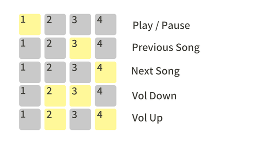
Mode A: Media Controller (Work with Youtube or other streaming service with playlist), see the attached key combination sequence instruction
Mode B: Typing demos (Auto URL open, Unicode characters and non-unicode characters)
Additional GPIOs
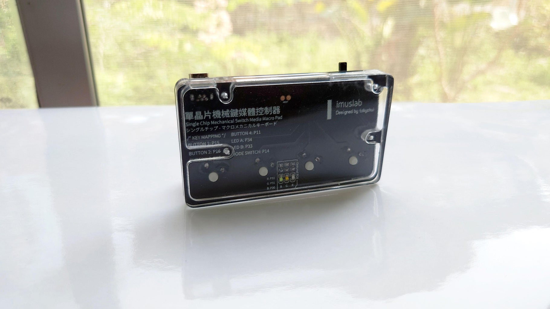
The PCB comes with 3 additional GPIO which I have pulled out from the IC as the RGB LED on the bottom of the macropad PCB. The corrisponding Pins for those RGB pins are P30, P31 and P32 as labeled on the silkscreen. You can feel free to use them for something else, like a vibration motor, some other electronics or even communicate with anotehr MCU using software serial or softi2c.
Step 7: Download Macro to Keypad
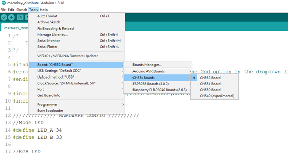
To upload your finished macro to the keypad, select CH552 in the board manager.
Click the upload button and while it is compiling, press and hold the PROG button on the PCB, then plug the macropad into your computer at the moment where the compilation is done. After plugging the macropad into your computer, release the PROG button and wait for the compiled sketch to be downloaded to the macropad.
The timing here is quite important. If you release the PROG button too early, Windows will try to reload your device and forcing it into USB HID mode again. If you release the PROG button too late, as the PROG button is shorting the USB D+ line, your program might not be able to upload.
Try a few time if you have issue with the uploading and I get it right on the 3rd tries :D
Step 8: Your $3 Macropad Is Now Completed!
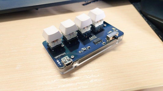
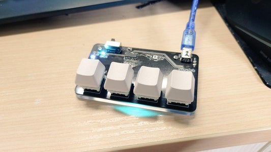


Now, you got yourself a little cute, low cost and good looking macropad where you can carry it to events and show off to people who also love mechanical keyboards!
Everything is open source on Github. You can find the source to the models, gerber files, source code and other detail information over at my Github repo
https://github.com/tobychui/4xMacropad
Thanks for reading till the end of this Instructable. If you have more ideas or improvements to share, feel free comment below or fork the source on Github and make your own!

![Tim's Mechanical Spider Leg [LU9685-20CU]](https://content.instructables.com/FFB/5R4I/LVKZ6G6R/FFB5R4ILVKZ6G6R.png?auto=webp&crop=1.2%3A1&frame=1&width=306)


