

Introduction: Inexpensive 3D Printed Joystick


Arcade games are super cool, but what really makes them stand out from your bog standard computer game is the chunky buttons and most importantly... a joystick!
If you're like me and love an engineering challenge or want to build something yourself rather than ordering it from overseas, this instructable is for you.
If you already have a 3D printer or know someone who does, why not put it to work? All you need to do is a bit of CAD in Fusion360 and salvage some old parts and you've got everything you need for this weekend project!
This is a quick and easy tutorial on how to make a 3D printed, fully customisable arcade joystick using Fusion360 for your next arcade machine.
Supplies


For this project you will need:
- A metal washer (Mine was M8)
- Around 110mm of 7mm diameter steel round bar (You could also use a bolt and cut the head off)
- 4x M3 bolts at least 30mm long (You can cut down longer bolts if you don't have any on hand)
- 4x M3 nuts
- 4x Limit switches (With normally open terminals - if they have both normally closed and open terminals that is fine)
Tools needed:
- A 3D printer (Build volume can be small as no parts are larger than 65mm in any direction)
- A way of cutting your steel rod to size - e.g. hacksaw, angle grinder etc.
- A screwdriver/spanner to tighten your bolt heads (Nuts recess into a slot so are held in place by print)
Note: I managed to salvage almost all the parts for this project for free. Springs are very common in old appliances such as printers, as are metal rods. M3 bolts are some of the most common sized bolts used for household appliances and chance is you have some left over from an old project. An M8 washer can normally be bought at your local hardware store for a few cents. Limit switches can be found in appliances such as washing machines or other devices that require a method to detect when a door is closed (or similar).
You can build this joystick for around $1 of filament (I used PLA), every other part can be salvaged for free.
Disclaimer: Before taking apart any appliance make sure you follow all the necessary safety precautions to keep yourself safe. Make sure you fully understand the safety risks of opening old and especially broken electronic devices as electricity can kill. If you have any doubt at all, for an extra few bucks you should just order the parts online to prevent harm to yourself or others. Salvaging parts should be done at your own risk.
Step 1: CAD Design in Fusion360


I have attached my Fusion360 file as well as a step file for you to view and modify this model to your needs. There is an annotated image above as well as a cross section which should help you to understand how this mechanism is put together and the names of all the parts.
The way it works is there is a main metal shaft with 2 printed disks on it. One holds the spring in place whilst the other holds a washer which helps to prevent plastic-on-plastic grinding when it is pushed against the restrictor plate by the spring. The restrictor plate is what defines the type of motion of the joystick by restricting its movement. The main body conceals the disks and the spring whilst applying a compression force against the spring. The main body is bolted flush against the restrictor plate. Additionally, a switch plate is bolted on, which holds the switches in place. An end stop is pushed onto the end of the shaft where the switches are located, the shape and orientation of this is very important and can be changed to adjust the sensitivity of movement. As the rod is moved around in a joystick movement the end knob pushes against the triggers of the limit switches. The remaining metal shaft is inserted into your electronics panel through a slightly oversized hole (the thicker your panel the larger the hole needs to be), then fastened with screws/bolts through the holes in the main body's flange. Then finally from the upside of the panel, you can add the dust cover and the ball knob. You can adjust the shaft length by pushing the entire shaft through the mechanism.
The wonderful thing about Fusion360 is how easy it is to render and animate parts. This comes in handy when sharing projects with other people so that they understand what each part is. You can see a short animation below that illustrates how all the parts go together, however in the following steps, I will show you in-depth how to put the mechanism together and how to wire it up.
(Make sure to turn your quality up to 1080p or HD for the best look!)
You can download the Fusion360 and step files below. There is also an STL for those of you without 3D modelling software if you want to view it but do not print it, the individual STL files are in the next step. (You can also use the "View in 3D" function of Instructables to view the models)


Step 2: Get Printing!

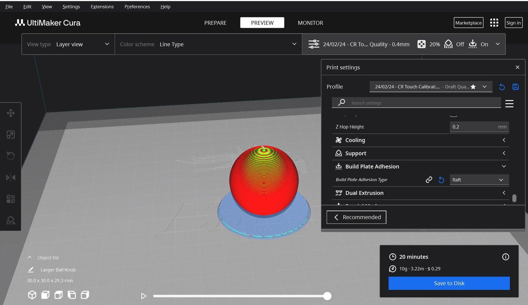

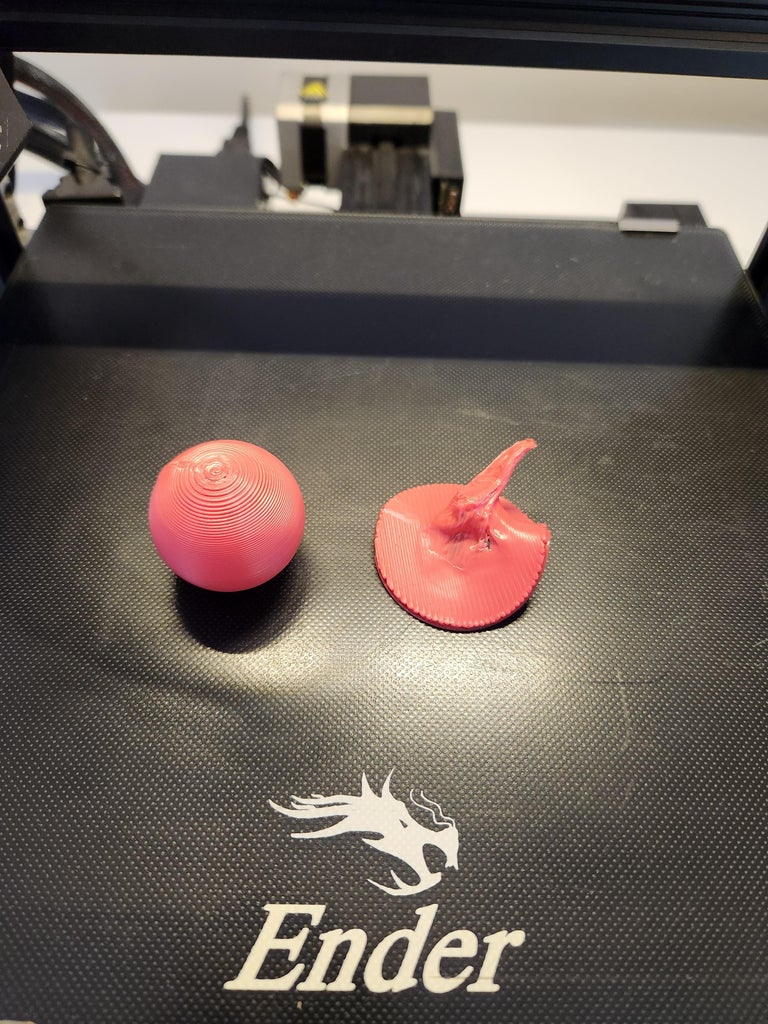
Time to get your 3D printer working! This can all be printed in a day, and will only cost around a dollar of filament. I used standard PLA on my Ender3 V2 and had no issues printing the parts. You don't need any supports if the models are orientated correctly (Flattest face down). Make sure you have dialled in your 3D printer settings as you want a tight friction fit of all parts on the rod, if you are not sure about your settings, try printing one of the disks and then move onto the end stop to test.
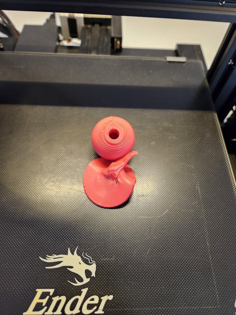
My printer struggled to print the knob without a raft as it wouldn't stick to the bed due to such a small surface area. Those with better bed adhesion might not have any issues. A tip if you are printing with a raft, if your part gets stuck to it and you can't get it off, heat the bottom of the raft with a lighter/heat gun and then pull the slightly softened plastic raft apart from your print with pliers (so that you don't get burnt). You can see in the photos where I have done this.
You can find the files as well as some print settings here on my printables: STL Files
Step 3: The Main Bar


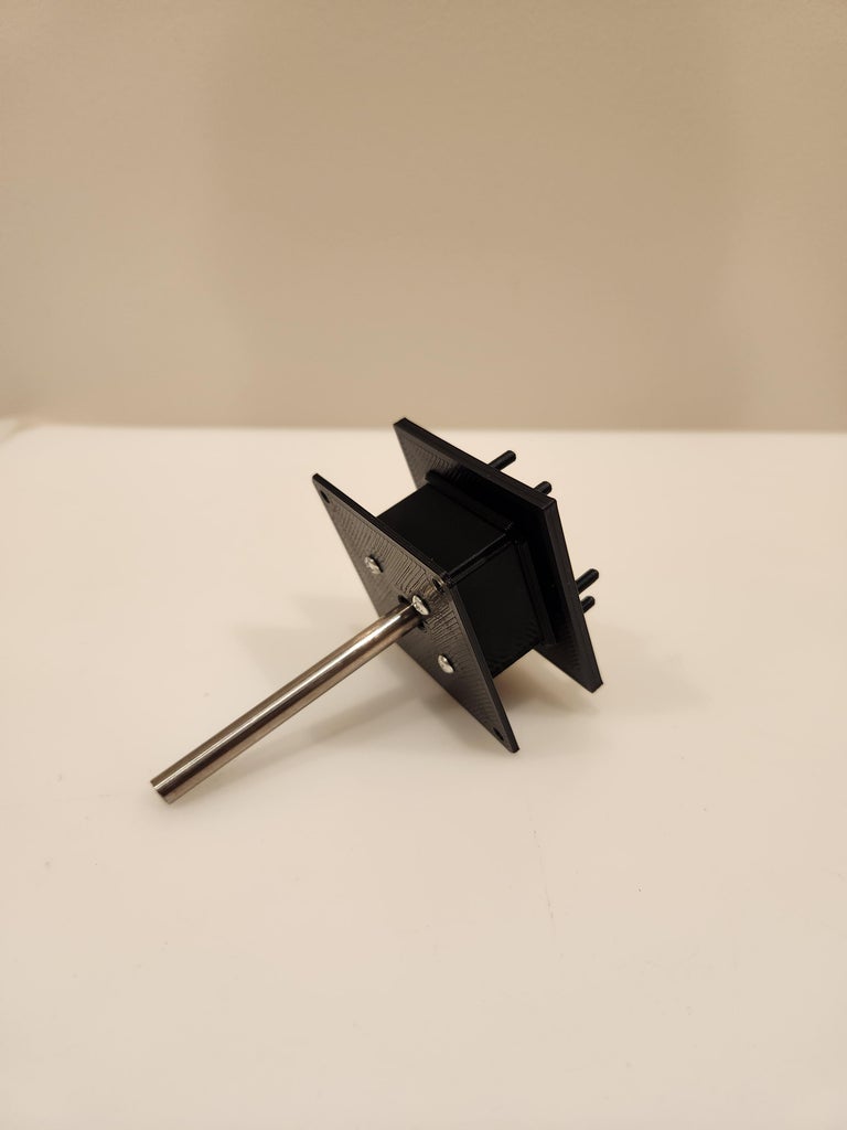
The first step after everything is printed is to assemble the main bar. Make sure your washer fits nicely on your washer disk and then slide both washer and spring disks on the steel bar once it is cut to size (100 - 110mm works well in my case). They should be just over a third of the way down one end with the washer disk closest to the end and the washer facing outwards (As seen in the photos).
If your washer is fatter than mine you can use the extended washer disk file under "Modified" parts.
Step 4: Choosing a Spring


Now to choose the spring. You want one that is longer than the main housing so that it is compressed when the restrictor plate is bolted on. However, you also want one strong enough such that it forces the steel rod to centre itself once let go.
Tip: If you have 2 springs that are the correct length but too weak, you can roll them into each other (as shown in the third photo), that way they are the same length but double the strength. Similarly, if your springs are too short but have the correct strength, you can place them end-to-end such that they become twice the length but maintain the same strength.
If you roll two or more springs together you might find that the collar on the spring disk isn't long enough, in that case I have included an extended spring disk file under the "Modified" folder (There are also modified fusion360 and step files if you need to make further adjustments).
Once you have got your spring, it should just fit over the collar on the spring disk as seen in the fourth image.
Step 5: The Restrictor Plate


The restrictor plate is what defines the movement of the joystick. With a clover/star-shaped restrictor plate you only get single-direction motion (i.e. left, right, up and down). However, with the circle-shaped restrictor plate you also get diagonal movements (i.e. left and up etc).
You can further experiment with different shapes of cutouts in the restrictor plate by modifying the 3D models provided. I used the circle restrictor plate when constructing mine.
The restrictor plate goes between the washer and the end stop (which will be explained later). For now, simply let it loosely rest on the same end as the metal washer with the flat side facing away from the disks and therefore the indented side facing towards the disks.
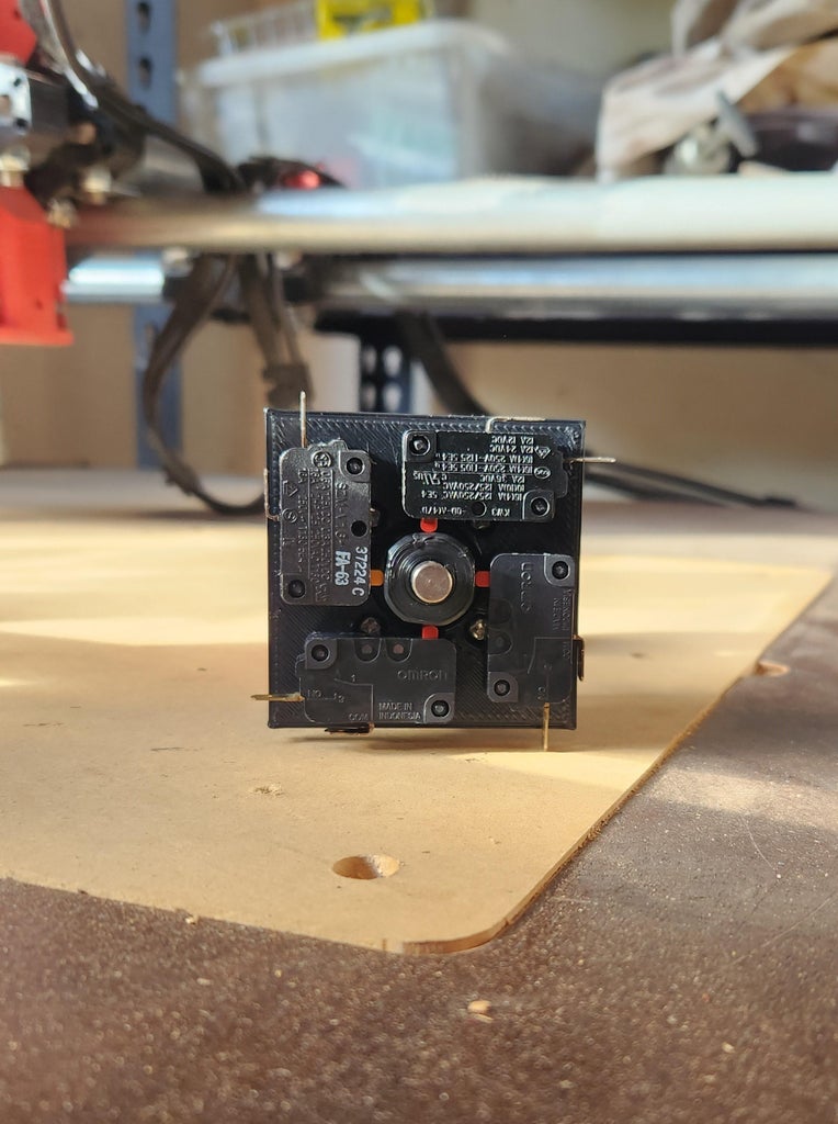
Step 6: Choosing Your Limit Swtiches
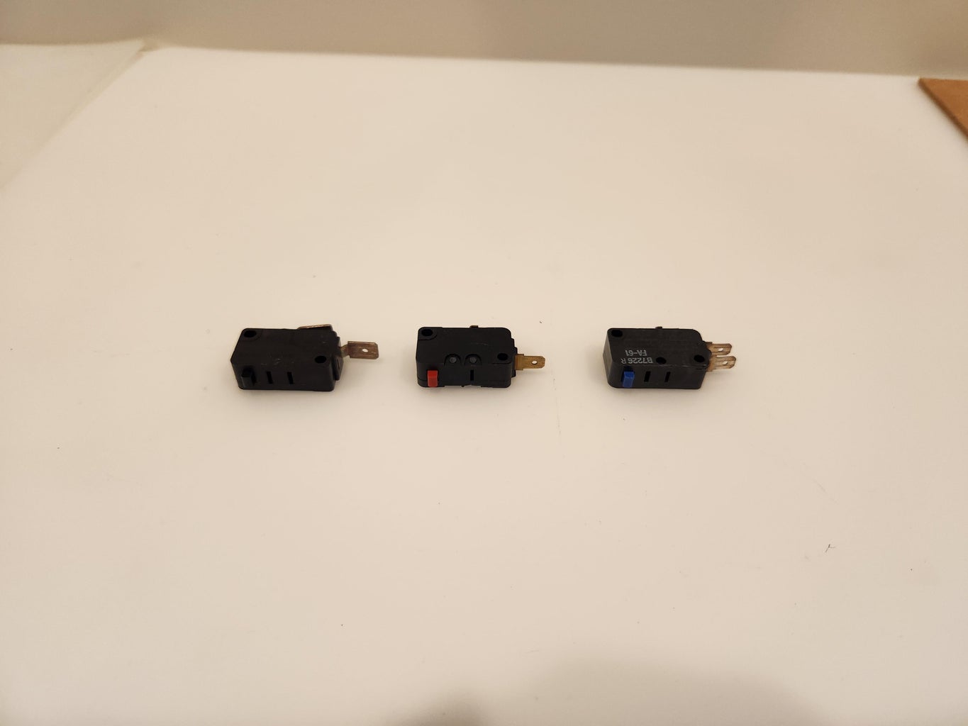


There are 3 types of limit switches commonly used. Normally closed (NC), normally open (NO) and ones with both. NC means that when the switch is not pushed down electrical signals can flow between the terminals, this is no use to us as it will trick the motherboard into thinking we are going in all directions except the one we are actually going.
NO means that no signals can transmit unless the limit switch is pressed down, this is what we are looking for.
There should be writing to tell you what each terminal is, which is often printed onto the sides of the switch however, you could also test terminals if you have a multimeter with a continuity test mode. Otherwise, you can wire an LED to an appropriate power supply and test if it only comes on when you push down the button, or if it stays on and only turns off when you push the button down (This means the switch is NC and no use for this project).
Note: One terminal will be common (C) and this is a common terminal between the NC and NO terminals if your switch has both.
In the photo above you can see a limit switch that is NC (Black), NO (Red) and one with both (Blue).
Once you have got 4 limit switches with NO terminals you can continue to the next step.
Step 7: The Main Housing and Switch Plate


For this step, you will need all the previous parts as well as the main body, switch plate, M3 nuts and bolts.
First of all, press fit the M3 nuts into their hexagonal cutouts in the switch plate. Then get the main body and line up the spring attached to the spring disk on the metal rod (For clarity the spring is not attached to anything in the image but yours should be on your metal rod). Then take the switch plate and position it such that the side with the points is facing away from everything else. Then thread the bolts through the main body and restrictor plate, until you can tighten them into the nuts in the switch plate. This can be hard to do as you need to compress the spring as you try to tighten the bolts so an extra pair of hands can help. Make sure the restrictor plate's indent lines up with the walls of the main body.
After you manage to get one bolt in, insert and tighten the rest. It should end up looking like the images above.
Step 8: The End Stop


The switch knob/end stop is a critical part of this design, it is the part that is moved as the main shaft moves and is the part that pushes against the switches. You can modify the knob to make it more or less sensitive, make it easier or harder to trigger a diagonal movement, or make it interact more or less with the restrictor plate.
To adjust the sensitivity you want to modify the overall top diameter. This will mean you need to make it wider or thinner, creating a larger or smaller gap between the switches (image 1 vs 2).
To adjust how easy it is to press 2 switches at a time, and hence send a diagonal movement command you can change how flat the four faces are on the switch, the flatter the easier it is to press 2 at the same time (make sure the diameter is wide enough to push down 2 switches). You can see the difference in images 2 vs 3.
To change how much it interacts with the restrictor plate, you can change the diameter of the lower section. Making it smaller means it interacts less.
Once you have chosen and modified your knob to your liking, you can print it and push it on the end where the switch plate is situated. This should be a very tight fit and should be pushed up against the washer and washer disk.
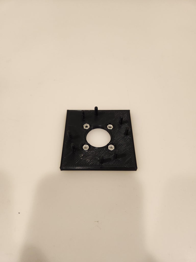
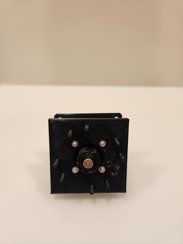
Step 9: Mounting the Switches


To mount the switches you can simply slot them over the pins on the switch plate. They should form a + symbol with their buttons as can be seen in the second image. They should be a tight fit, however you can add a touch of hot glue to the underside to hold them firmly in place. If your bolts are too long it will prevent you from mounting your switches, you can either cut down the length of your bolts, or you can extend the X-shaped raiser under each switch before printing the switch plate to raise the switches up higher. If you do this remember to also increase the length of the pins, end stop and overall length of your metal rod. I would recommend simply cutting your bolts to size.
You should now have a fully functional joystick! It should be able to move like in the video below:
Step 10: The Joystick Knob


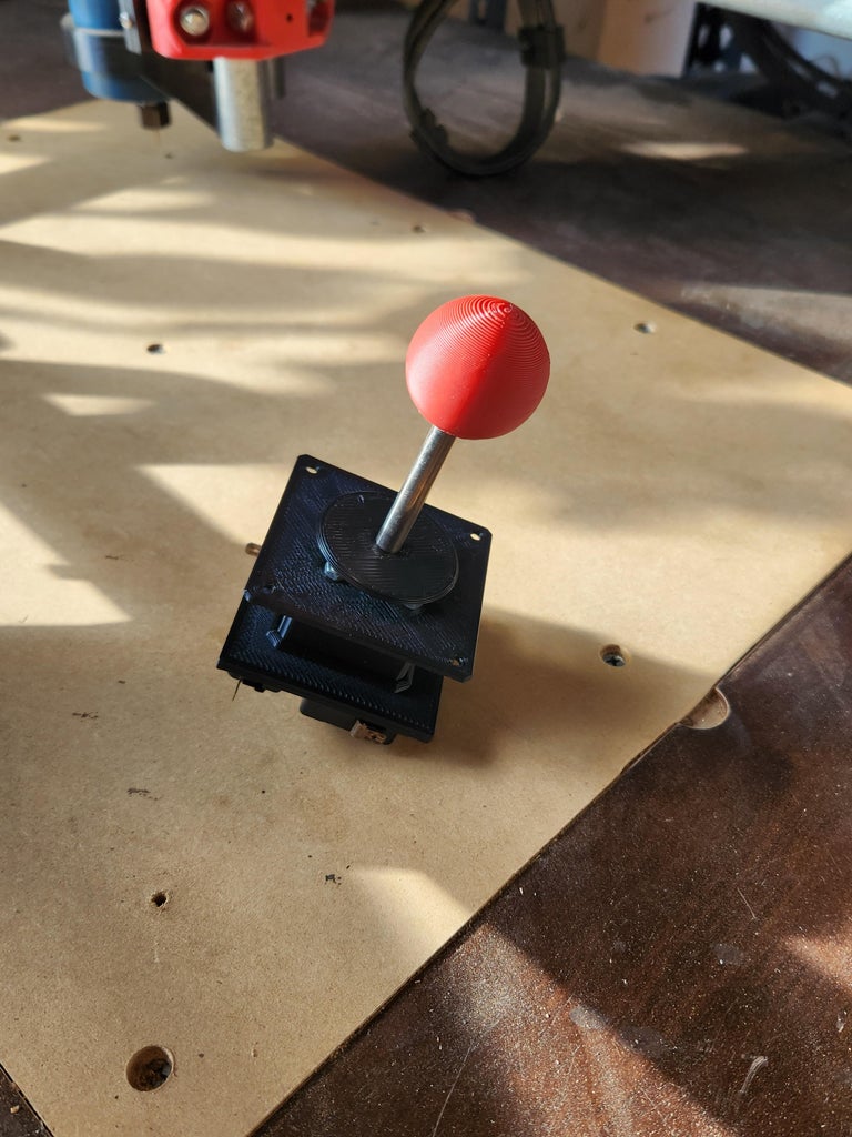
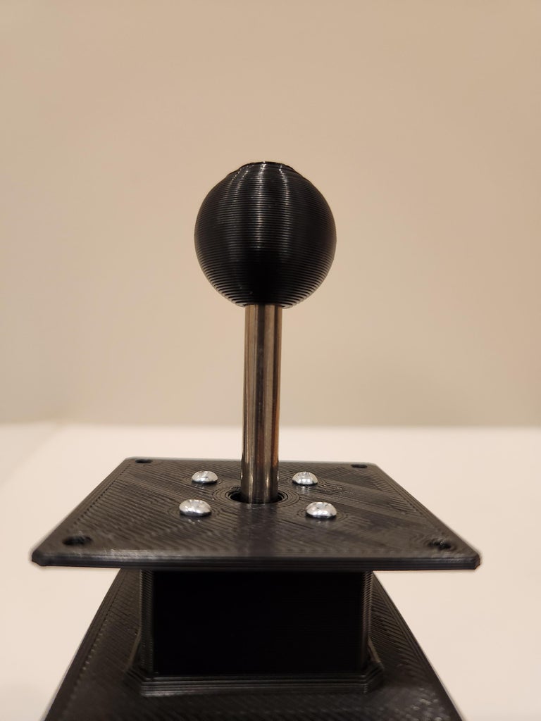


The joystick knob and the dust/hole cover are the very last parts of the mechanism. You should first mount the main body to the underside of your project panel before adding the hole cover (flat side down) and then finally pushing on your knob of choice.
You can print the knob in any shape or size so long as it has a 7mm hole to insert into your metal rod.
If you need help building a project panel for your joystick and buttons I have just the Instructable to help you out!
Step 11: Wiring It Up


To wire up the joystick, connect all common (C) switch terminals to ground/the negative wire, and each NO terminal will be for their respective movement. This can now be incorporated into any project you are working on or can be wired into a USB interface for a joystick and buttons. For neatness, you can wire them all into a 5-way header.
The following wiring diagram was done in Fritzing and you can access the file below.
Attachments

Step 12: LED Proof of Concept

To show that the joystick works I have hooked it up to some LEDs in a matrix so you can see the joystick in action. There are 2 videos below to illustrate that.
Step 13: Customizability

The best part of building something yourself is the fact you can customise it to your needs and liking. You can modify any of the parts as I have included all files. Maybe you want 5 or 6 switches rather than 4, maybe you want a switch on the bottom so you have 4 axes of motion as well as a push button (similar to a rotary encoder). Or maybe you just want a cool custom knob of a skull or anything else you can imagine. All you need to do is add a 7mm hole partially through the model and now it is a totally viable knob!
I hope this Instructables has inspired some people to try this project as it is super fun, takes very little time, and costs almost nothing. Remember to post photos of your makes and any improvements you've discovered below!
Runner Up in the
Arcade Student Design Challenge

![Tim's Mechanical Spider Leg [LU9685-20CU]](https://content.instructables.com/FFB/5R4I/LVKZ6G6R/FFB5R4ILVKZ6G6R.png?auto=webp&crop=1.2%3A1&frame=1&width=306)


