

Introduction: DIY Arduino Word-Clock Project


This instructable is on the construction of my Arduino Word-Clock. This instructable brings together a couple of my previous sub-projects that have been published on instructables as I have progressed to the completion of the Word-Clock.
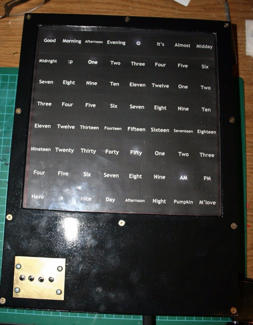
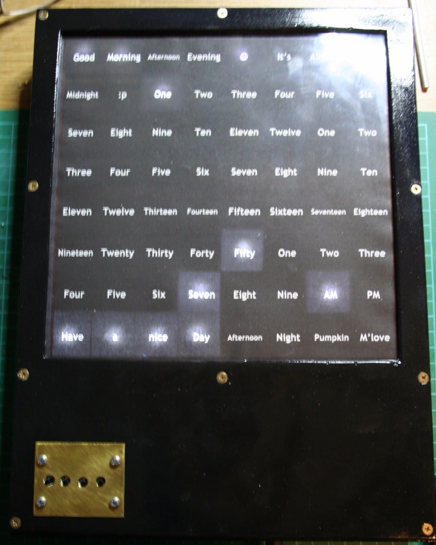
So, what is a Word-clock? It is a clock that has an 8 x 8 cell matrix with the words and numbers arranged in a way that a person can read the time as a phrase. For instance, 01:12 would be phrased as "Good Morning, It's One Twelve AM, Have A Nice Morning". The clock face is simply a sheet of paper, with all of the words printed on it that are arranged to fit within the 8 x 8 cell matrix, which is the same size as the LED matrix beneath it.The relevant cells are highlighted by lighting an LED under the appropriate combination of words.
I first saw a Word-Clock some time ago and wanted to make one.
Here, then, is my interpretation of the Word-Clock.
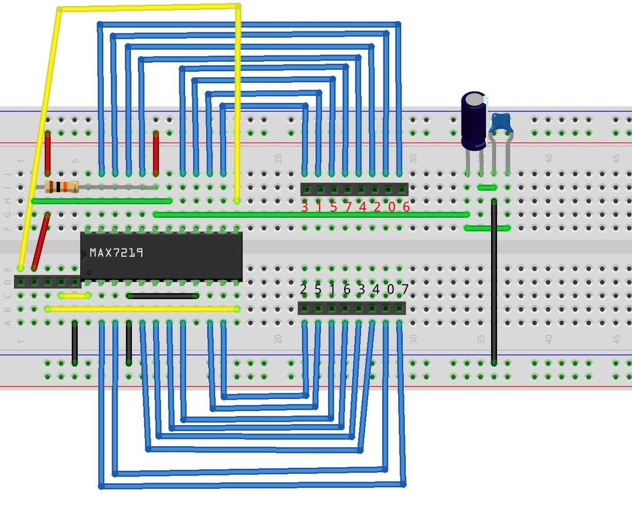
The LED Matrix is a home made 8 x 8 LED Matrix and controller based on the MAX7219-CNG LED Controller IC and can be found here.
The "Arduino" used is another home made small footprint DIY-Arduino which can be found here.
I am using a DS1302_RTC, that I bought from eBay, as the Real Time Clock module which drives the time functions.
There is also a very simple Tactile Momentary Switch Array that I built as an interface for setting the time.
Additionally, the case was constructed using some 10 mm x 400 mm pine from the hardware store, a bunch of screws, glue, acrylic sheet and the clock face is printed on plain paper.
Because I used home made parts, I was able to fit the components nicely into a case of my design without having to work around the size and shape constraints of off the shelf components.
The biggest challenge, for me, was the programming element of the project. But we'll get to that ;)
Step 1: The Case - a Word on Construction


The case was made to fit the 8 x 8 LED Matrix, which is a 220 x 220 mm square approximately 30 mm deep.
I made a frame that slotted the LED Matrix in (from the back) and then built a larger frame around that leaving a 150 mm void at the bottom where I placed the components.
When fitting the inner frame to the outer frame, I left a 4 mm space between the top of the inner and the outer frames to allow space for a 4 mm thick acrylic sheet.
The back and front of the case are made from 4 mm plywood. The front face of the case has a 200 x 200 mm square hole cut in it which reveals the acrylic sheet and clock face. I also drilled some holes in the face for the buttons to poke through.
The case also has a 12 mm hole drilled through the bottom to allow the power plug to pass through to the power socket on the Small Footprint DIY-Duino board.
I fitted a standard picture hanger onto the back of the clock along with some rubber feet to make sure that the clock will sit nicely against the wall when it is hung.
I made a couple of these cases while trying out different design ideas. There is no "right" way to do this, let your needs and design guide you. Of course, you need to be mindful of the overall design constraints of the size of your LED Matrix and the components you are going to house. You could, for instance, make the case deeper and make it square, rather than rectangular ... surprise yourself!
Attachments

Step 2: Fitting It in - the Gubbins
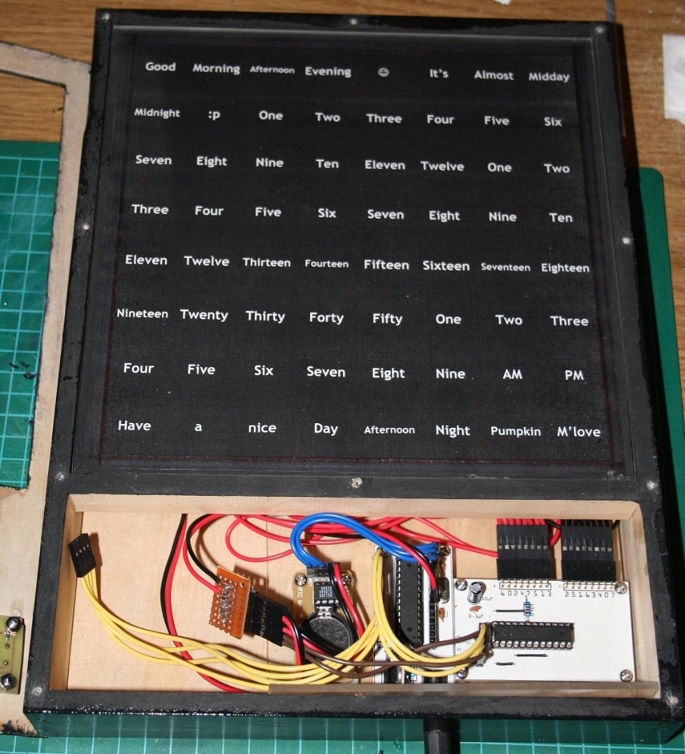

The arrangement of the components within the case is fairly straight forward. I brought the 2 x 8 pin connectors behind the LED Matrix to connect to the LED Controller board on the bottom right.
The DIY-Duino is located in the middle and the DS1302_RTC is leftmost of the components.
There is a button array that is bolted on to the inside of the clock face (which isn't pictured above), so I've included the PCB view and the PDF so that you can make your own.
I made a mini-power board that serves the three sub-boards (LED Controller, Button Array, DS1302_RTC) from the DIY-Duinos 5V and GND supply ... at the moment, the mini-power board is "floating", but I'll probably mount it on to the case so that it doesn't rattle.
Step 3: Programming - the Word-Clock Sketch
I started with the open source DS1302 RTC sketch by "Krodal" as this had already codified the interface between Arduino and that module. There is a LOT in the example sketch and it is a marvelous piece of work, a great many thanks go to Krodal for that source.
On top of the Krodal source, I added code for enabling the 8 x 8 LED Matrix and button array, but, I also had to come up with a way to read and display the BCD formatted time data as matrix vectors.
My life was made a little easier by the decision that the clock would only care about Hours, Minutes and AM/PM states. I wasn't going to care about Leap Years or Daylight Saving Time.
The displayTime function gets the Hours and Minutes and then, through a series of case statements, turns the time into a matrix vector map.
The minuteString function is used by the displayTime function to refine the time display for minutes.
The plusTime function is used to increment Hours and Minutes and toggle between AM and PM.
There is an unimplemented minusTime function to decrement Hours and Minutes and toggle between AM and PM.
Finally, I've added a bunch of time management and button management to the loop structure.
I am using 4 buttons in the Word-Clock:
- Button A - Increments Hours
- Button B - Increments Minutes
- Button C - Toggles AM/PM
- Button D - Increments the LED Brightness
In all cases, the increment is a looping structure that returns to 0 when the value reaches it's highest value (HH = 0 - 12, MM = 0 - 59, Brightness = 0 - 16).

Step 4: It's Alive!
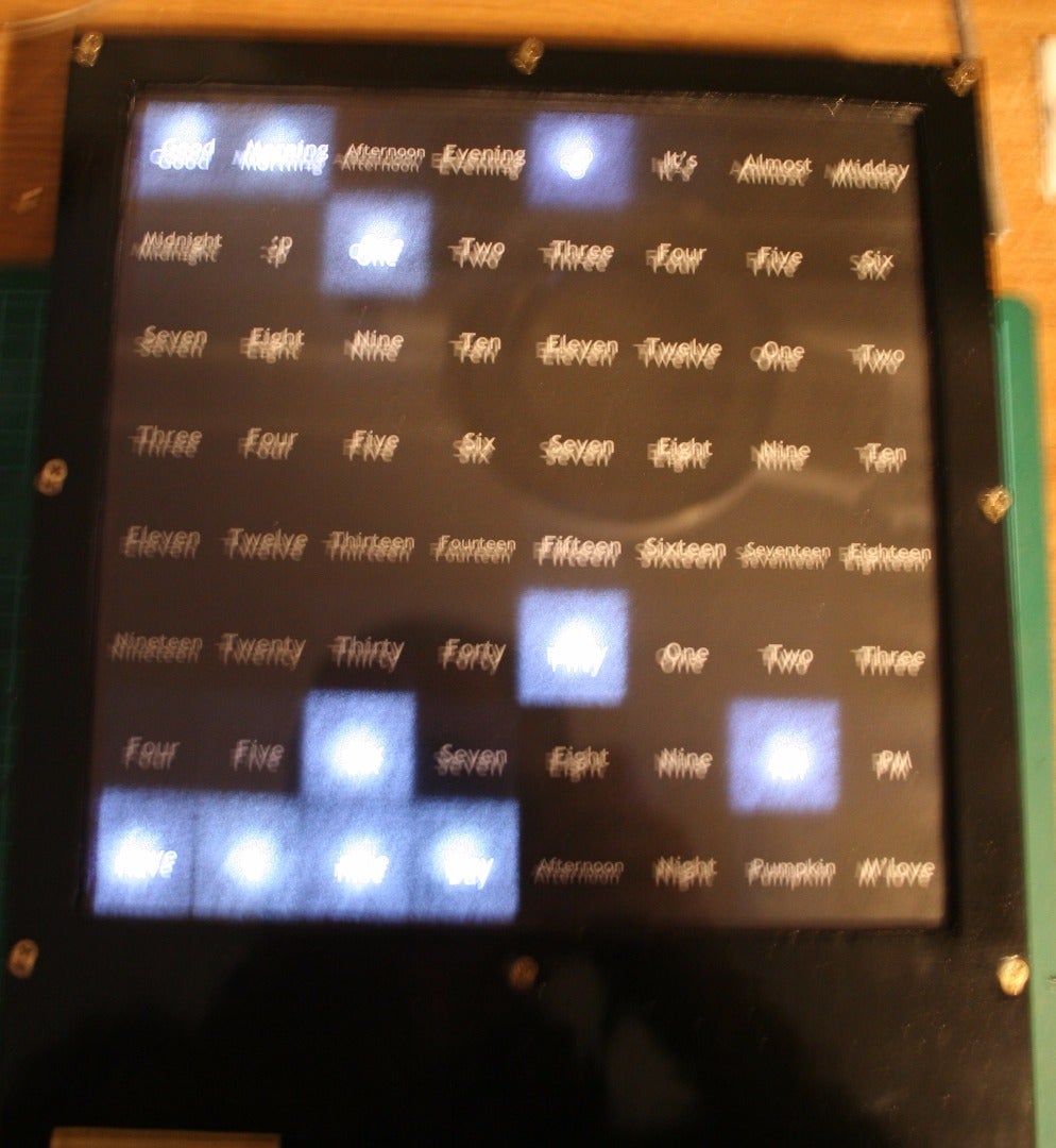
Finally, the Word-Clock works and I can sit back and enjoy my creation ... yeah, right ... I'm going to keep right on tinkering and modifying it!
I went through a couple of problems while making this project, not least of which was that when I changed the LED Matrix pins from 8 x 2 pin to 2 x 8 pin I totally messed up the pin order and had to go through the tedious hell that is methodically checking each cathode pin against each anode pin to get them back in order. Later, though, I had a problem where all of my rows were in reverse order ... it seems that problem was related to the earlier one. At least the row order problem was a very simple fix when I had worked out what the problem was.
My advice to you, dear reader, is label ... label your home made components, label your home made pins and, for the love of all that is sacred, write it down!


