

Introduction: DMS Workholding Templates


In this lesson, you will learn the steps for setting up a CAM file in Fusion 360 for the DMS 5-axis router. Then, you will learn how to prepare the inside of the machine for machining.
1) Open Fusion 360 and navigate to the CNC at Pier 9 Team Hub.
2) Bring your part into the correct template file using the steps in the video:
Recap:
--Navigate to the template file. Double click to open it.
--Drag part from Data Panel into active window.
--Move part until it's visible from all sides, then hit Enter.
Note that once you bring your part into the assembly file as a Component, Fusion creates an automatic link between the part and the assembly. This means that if you modify your model in the original part file, these changes will also appear in the assembly file. If you do not want your part to be linked, you can break the link by right-clicking the part and choosing Break Link.
3) Save the file under a new name using these steps:
Recap:
--Under File, choose Save As.
--Save in Master Folder under new name.
4) Create a joint between your stock and your part using these steps:
Recap:
--Use hotkey J to create a joint.
--For Component 1, click on the center bottom (or top) of your part.
--For Component 2, click on the center bottom (or top) of the stock.
--Flip joint around if necessary. Add an offset if you've joined the center top of the part and stock, to leave room for facing.
--Joint type should be Rigid. Click OK.
5) Edit the stock dimensions using the steps in this video:
Recap:
--In the Modify dropdown, choose Change Parameters.
--Under Favorites, change the stock dimensions and extrusion. Click OK.
Step 1: DMS CAM Setup
Now you're ready for CAM, Computer Aided Manufacturing.
1) Edit Setup 1 to verify the Work Coordinate System, Model body, and fixture:
Recap:
--Enter the CAM Workspace.
--Right click Setup 1.
--Verify that the Work Coordinate System is set to the center top of the receiver plate.
--Click Nothing next to Model. Then select the part.
If you are having trouble selecting the model, expand the browser tree on the left and turn off the visibility of the stock (under Bodies).
--Click 5 Bodies next to Fixture. Verify that the DMS stand and vise are selected as the fixture.
2) Continue editing Setup 1 to verify the stock and set the Work Coordinate System Offset to 7:
Recap:
--In the Setup dialogue, click the Stock tab.
--Verify that the Stock Solid body is correct.
--Click the Post Process tab.
--Change the program number to a six-digit integer.
--Change the WCS Offset to 7.
This changes the active WCS from G54 to G159 N7.
--Click OK to create Setup 1.
Step 2: DMS Post Processing
You have now set up your template file.
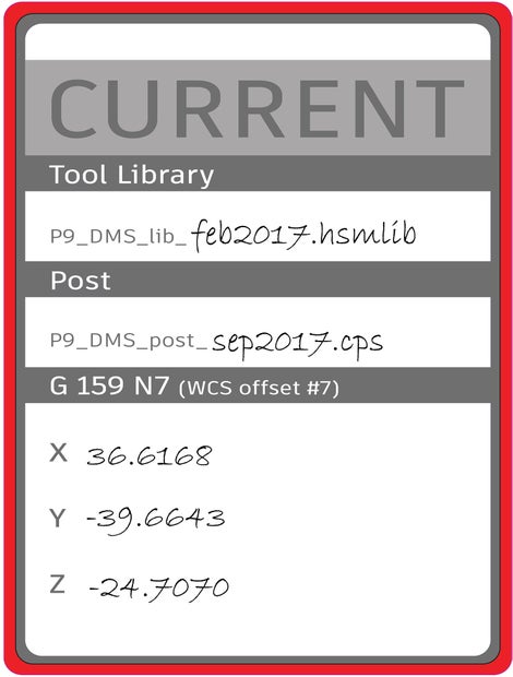
1) Before starting CAM, confirm that you are using the latest DMS tool library, labeled on the sticker outside the machine and available for download in the Pier 9 CNC Data Instructable.
The naming convention is: P9_DMS_lib_MonthYear.hsmlib
2) Finish your CAM toolpaths, simulating as you go.
3) After you are done with CAM and all toolpaths are verified, cut your stock. Take measurements with a caliper and update your CAM Setups.
This is especially critical because you will be skipping the step of setting G54 by jogging a tool to the back right corner of the stock (or wherever the WCS is set). If your stock dimensions are inaccurate, you could unintentionally put too much load on a tool.

4) When you are ready to post process, double check that you are using the latest DMS post processor, labeled on the sticker outside the machine and available for download in the Pier 9 CNC Data Instructable.
The naming convention is: P9_DMS_post_MonthYear.cps
5) Write a description comment, and then post your code to a USB drive.
6) In the editor, verify that after the first tool change, your code calls out G159 N7.
Using Ctrl + F, the Find command, can be useful when searching through G-code.
Remember that G53, in the code header, specifies the Machine Coordinate System. G159 N7 is the Work Coordinate System.

Step 3: From Software to Hardware
Now that you've posted your G-code, it's time to move into the CNC shop. The subsequent steps in this lesson take place at the DMS machine.
You'll learn how to set up the DMS stand, install the Lang vise, install the stock, and verify the Work Coordinate System, G159 N7.
Step 4: Setting Up Stand
1) Find the 3/8"-16 holes on the acrylic bed of the DMS that have been marked in blue. Use compressed air (on a hose behind the back right corner of the machine) to blow out chips. Use a scraper to remove any irregularities on the surface of the acrylic.

2) Place the DMS stand on the machine bed. Line up the stand's through-holes with 3/8"-16 holes in the acrylic.

3) Hand-tighten eight 3/8"-16 screws and washers to align the stand and machine bed.

4) In the Workholding drawer of the DMS Lista cabinet, select pin gauges 0.375" and 0.376".

5) On the right and left side of the DMS stand, place the registration pins through the stand and into the acrylic bed.
These pins precisely locate the stand to ensure that the Work Coordinate System G159 N7 is accurate and repeatable.
If you have trouble aligning the pins, try inserting pins 0.372" and 0.373", and then build up the final sizes.

6) Tighten screws with a 5/16" allen wrench.

8) Remove pin gauges and return to the correct location in the Workholding drawer.
Step 5: Attaching Lang Vise to Stand
If you are using a Makro Lang vise with rectangular stock, here are the steps for installing the vise and securing your stock.
1) Clean the receiver plate and vise with a dry cloth to remove chips and debris.
Any chips trapped between the two can damage the vise and receiver plate, and can cause tolerances to decrease over time.
If necessary, remove blue hole plugs by cupping your hand and using compressed air. For holes you will not need, replace blue hole plugs to prevent chips from getting inside the receiver.
2) Ensure the 8 mm allen bolt in the front of the receiver plate has been turned counterclockwise enough to allow the vise to sit flat on the plate.
3) Install vise by placing clamping studs in the bottom of the vise inside the holes in the receiver plate.
Ensure the front of the vise is facing you. The front jaw will have the letter L, indicating that the threaded rod that closes the jaws will tighten the jaws when turned clockwise. The front jaw will also indicate the maximum torque, 100 N m.

4) Secure the vise to the receiver plate.
Use an 8 mm allen driver on the blue handled torque wrench set to 30 N m. Review Lesson 2 for a reminder on how to set torque levels.
Tighten until the wrench disengages with a clicking sound.

5) Install stock in vise.
Center the stock in the vise jaws with the tick marks along the jaws. If needed, use calipers.
Use the 12 mm socket on the black handled large torque wrench, set to 100 N m.
Tighten until the wrench disengages with a clicking sound.

Step 6: Attaching 3-Jaw Chuck to Stand
If you are using cylindrical stock with the 3-jaw chuck, here are the steps for installing the chuck and securing your stock.
1) Clean the receiver plate and chuck with a dry cloth to remove chips and debris.
If necessary, remove blue hole plugs by cupping your hand and using compressed air. For holes you will not need, replace blue hole plugs to prevent chips from getting inside the receiver.
2) Ensure the 8 mm allen bolt in the front of the receiver plate has been turned counterclockwise enough to allow the chuck to sit flat on the plate.
3) Install chuck by placing clamping studs in the bottom of the chuck inside the holes in the receiver plate.
Ensure the front of the chuck is facing you. The 10.9 mm square socket should be slightly left of center.

4) Secure the chuck to the receiver plate.
Use an 8 mm allen driver on the blue handled torque wrench set to 30 N m. Review Lesson 2 for a reminder on how to set torque levels.
Tighten until the wrench disengages with a clicking sound.

5) Install stock in chuck.
Center the cylindrical stock in the chuck jaws and place in the "high" or "low" position.
Use a 10.9 mm square driver on the large black handled torque wrench set to 70 N m.
Tighten until the wrench disengages with a clicking sound.


Step 7: Verifying WCS G159 N7
While following the DMS Quick Start Guide, remember that you will not be setting the WCS (G54) by jogging a tool to the back corner of the stock, or wherever the WCS has been set. Instead, you will verify that the controller has the correct G159 N7 coordinates.
Replace pages 11-12 of the DMS Quick Start Guide with the following steps:
1) From the main menu on the DMS controller, press F5 (Tables).
2) Press F1 (Zero Offsets).
3) Use the arrow keys to scroll down to G159 N7.
Compare the numbers to the numbers stored on the sticker outside the machine.
If they are different, consult Shop Staff.

4) Press Main Menu to return to the main screen.
Step 8: Additional DMS Resources
Congratulations on completing the DMS portion of the Workholding at Pier 9 course!
Here are some additional DMS Resources. Note that we will provide links once they are available.
The DMS QuickStart Guide
A step-by-step guide for safe machine operation.

3D CAM and CNC class
A step-by-step guide for CAM and machining the DMS certification part, a wooden serving spoon. You will learn strategies for 3D toolpathing an organic shape with a flip in Fusion 360, as well as step-by-step instructions for executing your programs on the DMS 5-axis router.


