

Introduction: Direct Reading of LCD Using General Purpose IO


Difficulty:easy..Schematics, Soldering, C Programming
Lots of devices have LCD (Liquid Crystal Display) screens - your microwave, digital clock, and bathroom scale are a few common examples. More than once, I have want to be able to read the information from the screen and use it in some way. I have come across a few guides on directly reading an LCD screen, but most seemed to be copied from some other source, lacking any real information of how it actually worked.
In this Instructable, I will teach you how to read LCD screen data by monitoring the individual control pins using an 8 bit AVR microcontroller. This information can also be used to directly drive an LCD screen if that is your end goal, although I will not be covering that topic in detail.
Looking for something to do with this technology? Check out my Instructable on creating an IoT coffee pot level monitor!
Step 1: Parts and Tools

Parts and Tools
- Something with an LCD screen - I will be using this digital scale from Amazon
- Screw Drivers & Pliers - To open up the scale
- Wire Cutters & Strippers - To cut and strip wire
- Soldering Iron - To attach wires to the screen
- Hookup Wire - Very small gauge is fine for this low current application
- Multimeter - To measure voltage / resistance
- Hot Glue Gun - Useful for coating connections and holding things down
Circuitry Components
- ATmega328p - Used to read the state of the LCD screen
- 2 x 0.1uF Ceramic Capacitor - Decoupling Caps
- 1 x 10k ohm Resistor - Pullup for AVR Reset pin
- 1 x 22k ohm Resistor - ADC biasing
- 1 x 100k ohm Resistor - ADC biasing
- 1 x Normally Open Push Button - AVR Reset Button
- 1 x Voltage Regulator - I'm using an LD1086 3.3V LDO regulator
- 1 x 10uF Aluminum Capacitor - Regulator Stability
- 1 x 1uF Aluminum Capacitor - Regulator Stability
- Male Header Pins - To connect wires to breadboard
- Breadboard - for Prototyping
- Perfboard - If you are soldering an actual circuit
Additional Items
- AVR Programmer - I use the pocket programmer from Sparkfun
- Serial Enabled LCD Screen - To reprint what we are reading (from Sparkfun)
- Logic Analyzer - To see what the LCD pins are doing... I use this small one from Link Instruments
Step 2: Open It Up
Does anyone ever open anything down?
- Make sure your device is unplugged / remove any batteries!
- Look for screws that hold the device together (likely on the back / bottom)
- Remove any casing to reveal the inner circuitry
- Charged capacitors can be dangerous, so be sure not to touch anything on the circuit board!

In the image, you can see the insides of the digital scale. There is a circuit with mystery black goo covering the controller, a few load cells, zero (touch sensor) and unit buttons, and the LCD screen. Not so long ago, this circuit would be populated with numerous components that could produce relevant data. Now, it is a single, inaccessible MCU with an external EEPROM chip. It's like the designers don't want us to do this sort of thing... Even with no accessible data points, we can get the information we want by directly reading the LCD screen.
Step 3: LCD Connections
LCD screens are typically connected to a circuit in one a few possible ways...
- Socket Connection - Header pins going into a socket on the board
- Ribbon Cable - This sometimes plugs into a socket, but not always
- Direct Connection - The pins on the LCD screen board are held against the pads of the driver board by force
In the kitchen scale, the LCD screen sits in the frame, and the circuit board is held against it with a few screws. In this way, the driving pads on the circuit board are making contact with the LCD pins.

There is no soldered or cable connection. If the circuit is not tightly secured to the case, the connection to the LCD is lost - as evidenced by missing segments or a very dim screen. This can make it difficult to attach any additional wires to the LCD. If even a single LCD pins isn't making good contact with the board, part or all of the LCD will not work correctly.

The following image isn't of this exact circuit board, but it does demonstrate the LCD pads on the board...

Step 4: Adding Wires to the LCD
This is where things get a little tricky. As mentioned in the previous step, the LCD pins still need to be making good contact with the driver board pads. You will have to use your best judgement to determine where you can solder wires to the board. I also recommend using incredibly thing wire; mine is 30 gauge.

- Locate the pads that connect to the LCD
- Solder wire leads to each pad (use thin wire, and small amounts of solder)
- Solder the other end of the wires to a header pin (keep them in order!)
- Reattach the board to the LCD.
- Apply power to ensure the LCD is still working.
- Optional - Coat the wire-header connection with hot glue for durability and insulation
At this point, we have no idea what wire does what, but that's OK. As long as you kept them in order (pin 1 on the lcd goes to pin 1 of the male headers, etc), it will be easy enough to figure out! At this point, we should probably talk a bit about how these LCD screens work.
Step 5: Direct Driving of LCD
Most people aren't as interested in reading the LCD screen as they are in driving it, so the best way to learn how to read the screen is to learn how it is driven. One of the best explanations I have found is available in this Atmel Application Note - AVR340, but I will quickly go over the key points.
An LCD screen is a collection of segments that react to AC signals present on the control pins. The segments might make up an alphanumeric digit similar to a seven segment display, or they could be for a single icon on the screen such as the AM/PM text on a clock. One screen can have many segments driven by only a few pins - this is done through multiplexing.

A single pin is actually used to drive multiple segments, depending upon which of a set of COM signals is active at any given time. As mentioned above, the LCD is driven using AC signals, typically in the form of binary square waves (OFF or ON). However, the COM signals will have three states: OFF, 1/2 ON, and ON, where ON is full the source voltage. The linked application note gives the following example of this control scheme.

Notice, only one COM signal is active at any given time, and the LCD segment line will control different segments, depending upon which of the three COM lines is active. To enable a segment, the segment line needs to be out of phase with the COM line. In other words, if the COM line is HI, the segment line should be LO, and vice-versa.
The next step for us is to determine which of those LCD pins are COM lines, and which drive a segment!
Step 6: Finding the COM Lines
In this step, we are using a logic analyzer to find the COM signals. In reality, an oscilloscope can be used and will actually make finding the COM lines easier; however, O-scopes typically have much fewer inputs than an LA. Even though we are looking for an AC signal, we can still read it on the LA by setting the triggering threshold level.
The digital kitchen scale operates at around 3.3V DC, so I have set the trigger for my LA inputs at 2.5V DC. This will make sure I only see the positive portion of the pulse, ignoring all of the other undefined regions.
- Set the input trigger threshold to about 3/4 of the source voltage level
- Set the horizontal time scale in the range of 5ms / division
- Connect a wire to a known ground on the circuit (or the negative battery terminal)
- Apply power to the scale, ensure the screen is working
- Individually monitor a single Pin to see what the pulse looks like
- Repeat for all pins until the COM line(s) are found
In my experience, the COM lines are typically found at the end of the LCD screen; hence, they should be the first few of the connection wires we soldered to the board. They are easily distinguished from the rest of the signals...
- If using an O-Scope, they are likely the only signals that have three states instead of two
- They repeat at regular intervals (likely a 10 - 50 ms period)
- The state of the LCD screen does not effect the pulse pattern

The digital kitchen scale happens to have four COM lines which have a 32ms period. Each pulse is fully OFF or fully ON for about 4ms. These four lines have a permanently repeating pattern which never deviates, regardless of what is being displayed on the screen at any given time.
Step 7: Decoding the Control Signals
This step is by far the hardest, as it will require you to solve a puzzle of sorts in order to decipher what the control signals mean. The more complicated your LCD screen is, the more difficult this process will become.
The digital scale LCD has 16 control lines - 4 are the COM signals and the other 12 drive segments. We need to monitor every single pin for various LCD states until we can discover which LCD pin is responsible for which segment(s). Since there are four COM lines, each control line likely drives four different segments.
Determine all possible segments for your LCD screen.

This is every known segment of the kitchen scale LCD screen. Actually, only the b and c segments of digit 4 are ever active, but all other segments shown are valid.
Record the Pin States for a known LCD screen
Using the logic analyzer (or O-Scope) we need to record the state of every single pin for all of the COM states. As long as the screen doesn't change, these patterns will repeat indefinitely; however, if a single segment changes, that particular control signal will change for one of the COM lines.I have highlighted the states of a few different pins for COM signals 1 and 3. Notice, a segment is ON when a pin is out of phase with the COM lines - when the COM is HI, the Pin is LO and vice-versa.

Create a matrix displaying all pin states for known LCD screens.
The hard part is finding the pattern - that is, which control lines are changing as a single segment of the LCD becomes active or inactive. It's a good idea to write all of these pin states down for various screens with subtle changes in which segments are active.

In this table, I put a 1 for any control line that is active (out of phase) with any of the COM signals, as seen in the previous pin state image. It is very important to take note of every active icon on the screen - some of them might be connected in seeming random ways.
The best way to find the patterns is to record the pin states after subtle changes. For example, the exact same time displayed with AM and then PM, or a digit displaying 0 and then 8. Remember, there are no chips or wire traces in the LCD, so the order of the control lines will likely correspond to the order of the segments on the actual screen.
Notice that the state of pins 11 and 12 seems very similar to 13 and 14. Given that the screen displays 0.0, could this mean that pins 11 and 12 drive digit 1, while pins 13 and 14 drive digit 0? This makes sense, given that there are six active segments used to form a 0, and the seventh active segment in pins 11 and 12 could be the decimal place! Additional readings with a similar display will help. For example, switching the mode from fl-oz to grams will change the display from 0.0 fl-oz to 0g. Suddenly, pins 11 and 12 all turn off, but pins 13 and 14 remain unchanged. I think we have found a pattern!
Fill in the map connecting control lines to LCD segments.
After enough readings have been taken, the complete pattern will be discovered. Since we are not directly driving the screen, the only way to test theoretical connections is to write down what you think the pins should be for a given display, and then make that display happen - in our case, this is done by switching to a certain mode and adding weight to the scale until a particular combination of digits is displayed.

In the case of the kitchen scale, the pins were arranged in a manner that actually made sense! The alphanumeric digits were grouped together, in the same order of their display. The only lines that were in a random order were the various unit icons, but that was to be expected. This table shows what control lines drive what segments for a given active COM signal.
Step 8: LCD Reader Circuit Design
With a pattern (hopefully) found, we can create a circuit to read the LCD pins and do something useful with that data.
This circuit will be built around at ATmega328p microcontroller using all of the default fuse settings and no external clock source. Since the COM lines are analog inputs, we could read each one individually using the ADC, but this is unnecessary. The same effect can be achieved by reading just one COM line using the analog comparator, and then simulating the other three COM lines in software. You might also note that I do not have connections shown for pins 5 and 6. The reason is simple - I don't care about any of the data represented by those pins.

The analog comparator is really simple. We use R5 and R6 to create a bias voltage on AIN1. The output of this voltage divider is about 2.7V - similar to the 2.5V trigger threshold I used for the logic analyzer inputs! The COM1 line is fed into AIN0. Whenever the voltage on AIN0 rises higher than AIN1 or falls below it, the comparator will trigger. We will use this as an interrupt source to trigger the start of an LCD read cycle. This will also be used to keep our simulated COM lines in sync.
The last thing I want to point out are the connections to JP2 - I actually plan on taking full control of the digital scale. My circuit will be able to disable power to the scale and drive the mode buttons. I have opted to leave all of PORTC open. This frees the I2C pins for communication with other chips as well as a handful of analog inputs which might be utilized later. Your implementation will likely vary!
Step 9: Firmware - Overview
The complete source code can be found in this GitHub Repository.
To start, our firmware will read the LCD screen and then print that information to another LCD screen for comparison. The only problem with this is that the LCD screen we want to use is serial driven, and our serial port transmit pin is being used to read one of the LCD pins. This isn't a big deal, it just means data from that pin will be inaccessible.
The code to do this is the main-v1.0.c file in the repo. This code is written in C. It does not use any Arudino libraries because that's not how I role. These are the basic building blocks of our firmware...
On Boot, Configure AVR Device
- Set IO Pins
- Turn Off Unused Modules (to conserve power)
- Use Timer 0 to simulate COM lines 2, 3, & 4
- Use Analog Comparator to Detect Com line 1
- Use USART0 to write to a local LCD screen
In Main Forever Loop
- Read LCD Screen
- Print Scale LCD screen data to Local LCD Screen
Interrupt Service Routines
- Timer 0 - Sync with COM 1, used to simulate the other COM lines actions every 4ms
- Analog Comparator - Triggered when COM 1 goes HI, turns on Timer 0
Other Functions We Will Need
- Read LCD - Initiate a reading of the LCD screen... probably enable the Analog Comparator and wait
- LCD Printing - Transmit a byte, string, etc to the local LCD screen
Step 10: Firmware - Main-v1.0
As mentioned, the first version of the code will read the scale LCD screen and then write that data to a local LCD screen. This is merely a proof of concept... rewriting the data from one screen to another is fairly pointless! I believe I have commented the source code well enough for you to understand what is happening if you are at all familiar with AVR code, but I will go over a few of the finer points.
A few files are included:
- modules/avr.h - I include this in every AVR project I work on
- modules/lcd/SerLCD_2x16.h - Function Prototypes and Macros for writing to the local LCD screen
- definitions.h - All of our main macros and definitions
- util/delay.h - simple delay routines
The hardware modules are configured in the initialize_AVR() function found on line 486.
Analog Comparator
The analog comparator is triggered on the rising edge of COM 1. It then enables Timer 0 which simulates the COM 1 falling edge and the other 3 COM lines.
Timer 0
Timer 0 is setup to trigger an ISR every 0.2ms. A counter within the ISR will cause events to take place after so long (namely, ever 4ms), and a switch statement is used to perform different actions for each active simulated COM line. The state of the LCD pins is recorded for each COM line, and at the end of the cycle, the Timer 0 is disabled.
LCD Reading
The read cycle is started by the readLCD() function on line 311. This function simple enables the analog comparator and sits in a while loop until the read cycle has completed. The decodeDigit() function found on line 321 actually turns all of the pin state data into numerical numbers for each of the LCD digits.
LCD Writing
The LCD Writing Routines found starting at line 407 were written by me a while ago. They can also be found in the modules/lcd folder, but I copied just the functions I wanted to use to the main file so I wasn't compiling files from multiple locations. I think they are pretty self explanatory.
Main
In the Main function, the AVR device is initialized, and then enters a forever loop. Inside this loop, the LCD screen is read, and that data is decoded and printed to the local LCD screen for testing. Digit 4 is skipped, and I do not worry about the clock mode of the scale because I am not monitoring the AM/PM LCD pin segments.

In a previous version of the circuit, I was monitoring all of the LCD pins, hence my ability to print the clock mode data; however, the presented firmware cannot do this. Also notice the "&" symbol in the digits due to the Serial Transmit line used to print to this LCD screen stopping me from reading one particular Scale LCD pin.
Step 11: Firmware - Main-v2.0
The second version of the firmware is almost identical to the first; however, I have removed all of the LCD printing functionality. There are no more LCD_write() functions, nor is USART0 in use. The other major difference is the addition of the updateLevel() function. This simple routine packs the weight displayed by the scale into two bytes of data. These bytes will be transmitted over the TWI bus to another chip, but that is part of another project, so I haven't included that code here. You should also notice that at the start of the main, the code forces the scale into weight mode in grams. This is done so that the data being transmitted from this scale to the internet is always consistent.
The main loop now reads the lcd screen and creates the two level data bytes before delaying for 1 second., nothing more, nothing less. All of the hard work is handled by the interrupt service routines for the analog comparator and timer 0.
Step 12: Wrapping Up

I hope that by using this guide, you will be able to hack into any of your digital devices in order to read data from the LCD screen. As always, if you have any questions of comments, be sure to post them!
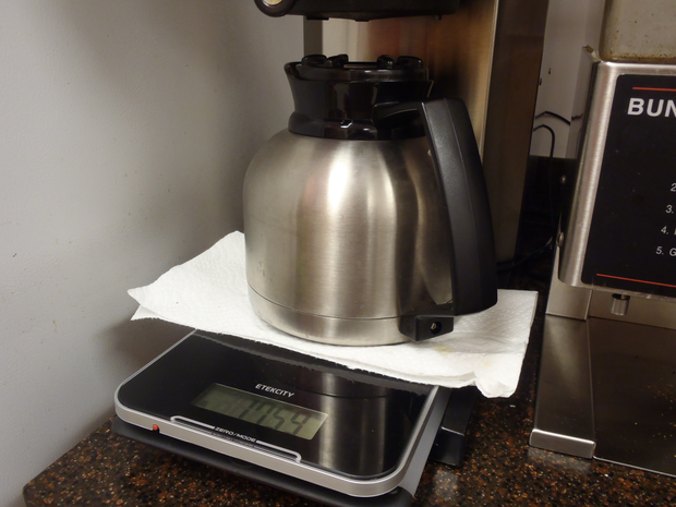
Like I said before, this project is actually part of a larger effort - building an IoT coffee pot level monitor. I have created a separate Instructable teaching you how to make it!

![Tim's Mechanical Spider Leg [LU9685-20CU]](https://content.instructables.com/FFB/5R4I/LVKZ6G6R/FFB5R4ILVKZ6G6R.png?auto=webp&crop=1.2%3A1&frame=1&width=306)


