

Introduction: ESP8266 WiFi Module for Dummies


Overview of the ESP8266 WiFi Module
The ESP8266 is a really useful, cheap WiFi module for controlling devices over the Internet. It can work with a micro-controller like the Arduino or it can be programmed to work on its own.
The Internet of Things (IoT) has just been made a whole lot cheaper and easier!
The ESP8266 comes with factory installed firmware allowing you to control it with standard “AT commands”. You can also easily create and upload your own code and this makes it hugely powerful and flexible.
The ESP8266 was launched in 2014 and is rapidly growing in popularity. There is only one ESP8266 processor but it is found on many different breakout boards. These all differ in terms of which pins are exposed and the size of the flash memory etc. These breakout boards have evolved rapidly over the years and there is a lot of information to be found on the web. This is both a blessing and a curse as some of the advice is outdated or just plain wrong.
As a result it took me 3 days before I could get it to do anything! Some people are lucky but for me it was a battle to get anything working. At times I thought I had broken it but with some perseverance it always came back to life!
I’ve finally got it singing and dancing and it turns out to be easier than I thought!
I’ve consolidated all the useful info I found into one place and I thought I’d share this in an instructable. This will hopefully get you quickly up and running with all the basic functionality that you’ll need.
In this instructable were are looking at the ESP-01 breakout board.
This same approach should however apply to most (if not all) of the variants of the ESP out there.
Step 1: The ESP-01 in a Nutshell

- It supports the 802.11 b/g/n protocol
- It can connect to your router and work as a client or it can be an access point itself or both!
- It is IP addressable and can be a Web Server
- The “standard” version has 2 digital pins that can be used for input or output. Eg: to drive LED’s or relays. These pins can also be used for PWM. Other versions have more pins exposed. For example the ESP-12, which is a good option if you need more pins. Either way the programming is still the same.
- Analog input is also available on the ESP8266 chip (ADC/TOUT) but it’s not wired up on the ESP-01.
- It can be combined with an Arduino or it can be programmed to work on its own
- There are various tools and development environments (IDE’s) to program it.
- And it has lots more….
In this demo the ESP8266 acts as a Webserver hosting a Web Page that you can interact with over WiFi.
With this demo you can start your own home automation project and control it from the web!
Step 2: What You’ll Need
Firstly let’s see if we can get it up and running.
A lot of sites recommend re-flashing the firmware and using various tools. You don’t need to do that just yet.
We’ll be replacing the firmware with our own code. In another instructable: The Simple Guide to Flashing Your ESP8266 Firmware I show you how to revert it back to an updated factory version. If you'll only be programming the ESP8266 with your own code - as we will be doing in this demo - then you don't need factory firmware. Your code is the firmware.
We'll be using the Arduino IDE as a programming tool but we don't need an Arduino itself. The ESP8266 has all the functionality we need.
Note: that after uploading your own code, your ESP8266 won't respond to AT commands any more. Your code has replaced the firmware. Using your code and the ESP8266 library in the Arduino IDE you'll have access to a richer set of commands. See the documentation here: https://www.arduino.cc/en/Reference/WiFi
You can restore the firmware on the ESP8266 to go back to AT commands if you wish. See my other instructable: The Simple Guide to Flashing Your ESP8266 Firmware.
NB: It’s a 3.3V module and not 5V. The ESP-01 is more robust than I thought but you should set it up properly, especially if you’re using it with a 5V USB to Serial Programmer or micro-controller, otherwise you may fry it!
What you’ll need:
- An ESP8266 of course (use the ESP-01 variant or adapt your wiring accordingly)
- Breadboard
- 3.3V USB to Serial Programmer like the FTDI Basic (sometimes known as a UART: Universal Asynchronous Receiver/Transmitter). Some come with a jumper to switch between 5V and 3.3V.
- Breadboard Jumper Wires
- A separate 3.3V Power Supply. You do need one as the ESP8266 can chew a lot of mA (>250mA at times). The 3.3V output from the Serial Programmer or the Arduino is not sufficient. Without a separate power supply your ESP may be erratic and you will waste time trying to upload code.
- Led, push button, 330 ohm resistor, 10k ohm resistor, .1µF capacitor across your power supply (as standard practice).
- Add a Logic Level Converter into the circuit if you’re using a micro-controller or FTDI programmer at 5V
If you have an ESP8266 with a built in USB port then you don't need to go through any of this hassle. The Wemos D1 Mini is a good alternative. See this: https://www.wemos.cc/product/d1-mini.html
Step 3: The Components in More Detail


ESP-01
I got my ESP-01 from: http://netram.co.za/2720-wifi-serial-transceiver-module-esp8266.html
You can have a look at the various versions here: http://www.esp8266.com/wiki/doku.php?id=esp8266-module-family
Breadboard Power Supply
A good power supply seems to be a crucial aspect for the ESP8266. A breadboard power supply is really useful, especially when you’re dealing with mixed voltages. The one shown here supplies 3.3V and 5.5V and plugs right into your breadboard. I should have got one a long time ago! The ESP8266 can chew a lot of mA (>300mA at times). If your ESP reboots or seems unreliable then you need a separate power supply for the ESP (keep a common ground though). Also connect a capacitor across 3.3V and ground to minimise spikes and to provide a small reservoir of power.
http://netram.co.za/938-breadboard-power-supply-5v33v.html
USB to Serial programmer
Get one that supports 3.3V or has a 3.3V/5V jumper otherwise if you only have 5V then you should use a bi-directional Logic Level Converter in between the programmer and the ESP8266. The FTDI Basic has a 3.3V/5V jumper on the back:
http://netram.co.za/2842-ftdi-basic-usb-to-ttl-programmer.html
http://netram.co.za/2679-logic-level-converter-bi-directional.html
Logic Level Converter
Bi-Directional 5V & 3.3V. This is only required if you are using a 5V serial programmer.
Breadboard Jumpers
Include some JST jumpers as they’re handy for plugging onto modules with pins and then joining them to the breadboard. Include some male to female cables for this purpose. The ESP-01 isn't breadboard friendly so you'll need these.
Step 4: The Breadboard Layout

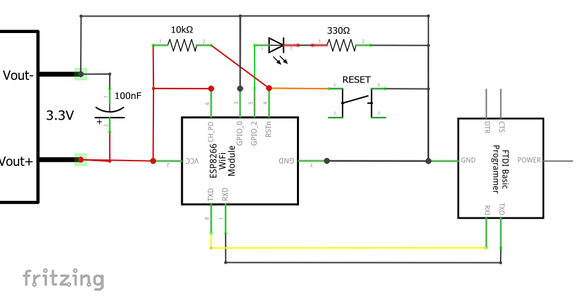
Looking at the breadboard, the FTDI programmer is the red board on top and the ESP8266-01 at the bottom. The FTDI programmer only needs 3 wires connected: the ground wire and the RX to TX and TX to RX on the ESP. On the left is the breadboard power supply (it would normally plug into the breadboard).
NB: The quality of the power supply to the ESP is one of the most important factors. There is a small capacitor (.1uF) across 3.3V and Ground to minimise spikes. If you are having problems with programming your ESP it may well be your power supply. What will help is to add another larger capacitor across 3.3V and Ground. eg: 10uF.
Step 5: The ESP-01 Pinouts

The picture above of the ESP8266 pinouts is found all over the net. I think it may have originated from Neil “Kolban’s Book on ESP8266”. This is a fantastic resource and is available as a pdf download from: https://leanpub.com/ESP8266_ESP32. It’s 400 pages long, was updated in November 2016, and if you’re into serious ESP8266 development then this is the book to get. It’s free but make a donation if you can.
Breadboard wiring notes:
- The wires are shown connecting to the front of the ESP-01 for clarity. Attach them to the same pins from behind. The ESP-01 is not breadboard friendly and JST connector male-female jumpers are handy for connecting it.
- GPIO 0 must be held low for programming. This should be removed if you remove the FTDI and operate the ESP8266 on its own power supply.
- CH_PD should be held high at all times.
- The RESET pin is held high with a 10k ohm resistor and brought to ground by the RESET button which will reboot the chip. Press RESET every time before you upload code, and every time you connect or disconnect GPIO 0. The reset button will save you a lot of hassle.
When you power the circuit up the red LED on the ESP-01 should light up and the blue LED should flash briefly. Later when uploading code to the ESP the blue LED should flash continuously during the process. Any other LED combinations suggests that there is a problem.
NB: If you want to remove the Serial programmer and run the ESP on its own, make sure you disconnect GPIO 0 from ground and push the RESET button otherwise the ESP may not work properly.
Step 6: Schematic
Step 7: Using the Arduino Instead of a Serial Programmer
You can also use an Arduino instead of your USB to Serial programmer.
A few things to note:
- On a 5V Arduino the digital output will be at 5V and this could fry your ESP2866. So either use a 3.3V Arduino or a Logic Converter chip
- The 3.3V Vout on the Arduino is insufficient to drive your ESP8266 and you could get unreliable results. Preferably use another 3.3V supply.
- As a recommended practice always upload a blank sketch to your Arduino before connecting any other devices to avoid any unpredictable results. A blank sketch has empty setup() and loop() functions.
- If you are using an Arduino Uno it only has one hardware TX&RX pair. To communicate with both the ESP8266 and the Serial Monitor at the same time you will also need to use the SoftwareSerial include file. It used to have a limitation on the baud rate but can now theoretically support a baud rate of up to 115200. A Mega 2560 has more hardware TX and RX pins so this could be a better way to go.
- And finally and importantly: Look closely at the TX and RX pins on the Arduino. You will notice that they have arrows next to them. The TX pin has an arrow pointing away from it. What this says is TX IN! What this really means is that the TX pin is actually the RX pin! And likewise the RX pin is actually the TX pin! So when using the Arduino as a serial adapter with another device you must connect RX to RX and TX to TX. I only discovered this nuance after several hours of pain! Why-oh-why did they label it like this?
Whilst I’m asking questions: why the ESP-01 was produced with so few of the useful pinouts exposed also baffles me! It is still a great starting point but if you need something more then go for the ESP-12.
To make things really simple, try an ESP-12 with a built in USB like:
Step 8: Programming Using the Arduino IDE
There are various tools to program the ESP8266 but the Arduino IDE (Integrated Development Environment) is by far the easiest for most folk.
To program the ESP8266 with the Arduino IDE you’ll need to download the latest version if you don’t already have it and then install the ESP8266 support. Note that you are only using the Arduino programming environment you don't need any Arduino hardware itself.
To download the Arduino IDE go to: https://www.arduino.cc/en/Main/Software
Start up the Arduino IDE and select the Boards Manager…
Step 9: Setup the ESP2866 Board Manager

Start the Arduino IDE and select the Boards Manager under Tools / Board ..
Step 10: Install the ESP2866 Board Manager

Find the esp8266, select it and click Install.
Step 11: Arduino Preference Setup

Go to File / Preferences
Step 12: Boards Manager URL's

In the Additional Boards Manager URLs field enter the URL for the ESP8266 package which is:
http://arduino.esp8266.com/stable/package_esp8266com_index.json
Step 13: ESP8266 Setup in IDE
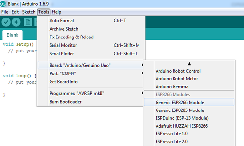
Select the “Generic ESP8266 Module” and go back to the Boards Manager again
Step 14: ESP8266 Options
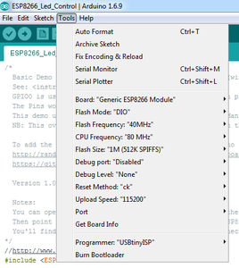
Setup you ESP-01 options. Select the appropriate COM port according to your PC.
Step 15: Talking to ESP8266
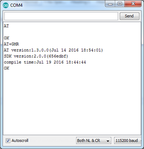
If you still have the original firmware on your ESP8266 you can try talking to it with the Serial Monitor.
- Open the Arduino Serial Monitor:
- Select the appropriate baud rate which is usually 115200 but could be anything down to 9600 depending on the firmware on the ESP.
- Also select “Both NL & CR”. Ie: New Line and Carriage Return characters after each “Send”.
- Type AT and press enter. The ESP should come back with OK. If not press the RESET button or try unplugging the USB cable and starting again. Make sure also that you have the right COM port selected. Also if you don’t have the “standard” firmware on your ESP it may not understand the AT command set. This is not necessarily a problem yet as you’ll be overwriting this with Arduino code later in this instructable.
- Type AT+GMR. This should come back with the version numbers of the firmware on your ESP. In another instructable I show you how you can restore the latest version of the “factory” firmware (if you want to).
Step 16: ESP8266 Arduino Code
Download code file (ESP8266_LED_Control.zip), unzip it and open it in the Arduino IDE.
Change the Router setting to yours. ie: change the SSID and PASSWORD fields.
Make sure your breadboard is setup correctly, and connect your USB cable to the Serial Programmer.
NB: When addressing the GPIO Pins in your code you should use the GPIO number. eg: 2 for GPIO 2 and not the physical pin number which will be different.
Attachments

Step 17: Uploading Your Code to the ESP8266

Make sure you’ve closed ALL Serial port monitors on the same port, if you you’re using them. Eg: tools like CoolTerm. Open the Arduino Serial Monitor again, as you will need to see the IP address of the ESP after it loads.
NB: To upload your code you must have GPIO 0 grounded. You can leave it there whilst running your code in the browser. Press the RESET button before each load. If the upload fails, check your settings and try disconnecting and reconnecting the USB cable. Try Ctrl&U a couple of times. If all else fails try rebooting your PC. Sometimes the COM ports get a bit messed up.
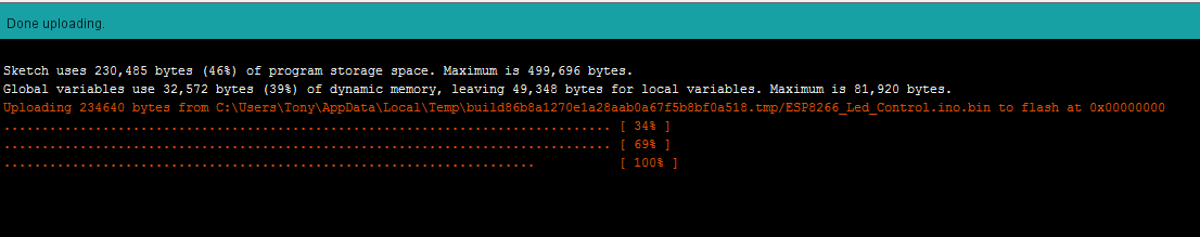
The blue LED on the ESP should flash if the code is being uploaded successfully. The progress of the upload should look like the images above.
NB: If you want to remove the Serial programmer and run the ESP on its own, make sure you disconnect GPIO 0 from ground and push the RESET button otherwise the ESP may not work properly.
If your ESP8266 uploads are behaving erratically, improve your power supply.
Step 18: Let See What It's Doing

Switch over to the Arduino Serial Monitor and you should see the IP Address of the ESP. You could also log into your Router and check what’s connected there. The device will show up in the list of connected IP’s with a name like: ESP_1A6C4A.
Whilst you are in your router you could always reserve the ESP's IP address and set up some Port Forwarding so that you can connect to the ESP from outside your network - like the office..
You should see something like the above. Use that IP address in your browser.
Step 19: Let's Try It Out

After clicking on a few links you’ll hopefully see the LED going on and off!
You also see that it can do PWM and dim the LED.
The ESP8266 can also handle Interrupts on the digital pins and also has analog input. The analog input pin though is not exposed on the ESP-01,
Internet Explorer works fine but for some reason FireFox seems very slow with the ESP. This may have something to do with the setup of the HTTP header.
Note: that after uploading your own code, your ESP8266 won't respond to AT commands any more. Your code has replaced the firmware. Using your code and the ESP8266 library in the Arduino IDE you'll have access to a richer set of commands. See the documentation here: https://www.arduino.cc/en/Reference/WiFi.
You can restore the firmware on the ESP8266 to go back to AT commands if you wish. See my other instructable: The Simple Guide to Flashing Your ESP8266 Firmware.
Step 20: ESP Resources
"Kolban’s Book on ESP8266" updated in November 2016 is for serious enthusiasts.
It is 470+ pages long and has an incredible amount of detail. You can get it for free but make a donation if you can.
https://leanpub.com/ESP8266_ESP32
He has now separated out the ESP32 and published a new book:
https://leanpub.com/kolban-ESP32
ESP32
"Like the ESP8266, the ESP32 is a WiFi compatible microcontroller, plus it adds support for Bluetooth low-energy (i.e BLE, BT4.0, Bluetooth Smart), and nearly 30 I/O pins."
See: https://www.sparkfun.com/products/13907
ESP Sites
http://www.esp8266.com/wiki/doku.php?id=esp8266-module-family
https://iotbytes.wordpress.com/esp8266-pinouts/
http://espressif.com/en/products/hardware/esp8266ex/resources
AT Commands
https://www.itead.cc/wiki/ESP8266_Serial_WIFI_Module#AT_Commands
https://espressif.com/sites/default/files/documentation/4a-esp8266_at_instruction_set_en.pdf
Arduino Boards Manager
http://randomnerdtutorials.com/how-to-install-esp8266-board-arduino-ide/
https://github.com/esp8266/Arduino
Notes on Flashing the Firmware:
I have published an instructable showing you how to flash the factory firmware onto your ESP8266.
See: https://www.instructables.com/id/The-Simple-Guide-to-Flashing-Your-ESP8266-Firmware/


![Tim's Mechanical Spider Leg [LU9685-20CU]](https://content.instructables.com/FFB/5R4I/LVKZ6G6R/FFB5R4ILVKZ6G6R.png?auto=webp&crop=1.2%3A1&frame=1&width=306)


