

Introduction: Easy Arduino Light Following Robot


This is a tutorial on how to make a light following robot using Arduino, it has been simplified so that beginners can attempt this project too. This project should only take you at the most of an hour. I hope you enjoy.
Step 1: Materials


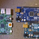
Arduino Uno: http://www.freetronics.com.au/products/eleven#.VZn...
H-Bridge shield: http://www.freetronics.com.au/products/hbridge-dua...
Chassis: http://www.hobbyking.com/hobbyking/store/__26249__...
2X LDR/Light Dependant Resistors
2X 100k Ω Resistors
Jumper leads
3X 9v
Step 2: Wiring


With the wires on the bread board that go to the side, 2 go to 5v on arduino and the other one goes to GND
It is easier to follow the pictures then me explain.
First, connect the H-Bridge shield to the Arduino Uno
Then, connect the LDR's, like in the diagram
After, insert the positive and negative of the motors in to the shield
*Now, connect 2 9v batteries in a series and then positive and negative to the spots on the shield
*Finally plug a 9v battery into the Arduino
(*Last 2 are for when you have uploaded the code)
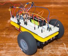
Step 3: Put It on the Chassis

Put the creation on your chassis how ever you please, make it look how ever you want as well. There is much I can say about this step though.
Step 4: Code
Please respect that it took a while to figure out and write this code:
//Code by Jason McLaughlin
//2015
const int channel_a_enable = 6; //start motor a /left
const int channel_a_input_1 = 4; //positive/negative 1
const int channel_a_input_2 = 7; //positive/negative 2
const int channel_b_enable = 5; //start motor b /right
const int channel_b_input_3 = 3; //positive/negative 1
const int channel_b_input_4 = 2; //positive/negative 2
const int RightSensor = A1; // Read the right sensor
const int LeftSensor = A2; // Read the left sensor
// Variable definitions
int SensorLeft; // This stores the value of the Left Sensor pin to use later on in the sketch
int SensorRight; // This stores the value of the Right Sensor pin to use later on in the sketch
int SensorDifference; // This value is used to determine the difference between the Left and Right
void setup() {
pinMode( channel_a_enable, OUTPUT ); // Channel A enable
pinMode( channel_a_input_1, OUTPUT ); // Channel A input 1
pinMode( channel_a_input_2, OUTPUT ); // Channel A input 2
pinMode( channel_b_enable, OUTPUT ); // Channel B enable
pinMode( channel_b_input_3, OUTPUT ); // Channel B input 3
pinMode( channel_b_input_4, OUTPUT ); // Channel B input 4
pinMode(LeftSensor, INPUT); // Defines this pin as an input. The Arduino will read values from this pin.
pinMode(RightSensor, INPUT); // Defines this pin as an input. The Arduino will read values from this pin.
digitalWrite(A1, HIGH); // Enables LDR
digitalWrite(A2, HIGH); // Enables LDR
Serial.begin(9600); // Enables a serial connection through the Arduino to either USB or UART (pins 0&1). Note that the baud rate is set to 9600
Serial.println(" \nBeginning Light Seeking Behavior"); // Placed at the very end of void Setup() so that it is runs once, right before the void Loop() }
void loop() { SensorLeft = 1023 - analogRead(LeftSensor); // This reads the value of the sensor, then saves it to the corresponding integer.
delay(1);
SensorRight = 1023 - analogRead(RightSensor); // This reads the value of the sensor, then saves it to the corresponding integer.
delay(1);
SensorDifference = abs(SensorLeft - SensorRight); // This calculates the difference between the two sensors and then saves it to an integer.
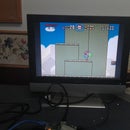
// This section of the sketch is used to print the values of the // sensors through Serial to the computer. Useful for determining // if the sensors are working and if the code is also functioning properly.
Serial.print("Left Sensor = "); // Prints the text inside the quotes.
Serial.print(SensorLeft); // Prints the value of the Left Sensor.
Serial.print("\t"); // Prints a tab (space).
Serial.print("Right Sensor = "); // Prints the text inside the quotes.
Serial.print(SensorRight); // Prints the value of the Right Sensor.
Serial.print("\t"); // Prints a tab (space).
// This section of the sketch is what actually interperets the data and then runs the motors accordingly.
if (SensorLeft > SensorRight && SensorDifference > 75) { // This is interpreted as if the Left sensor reads more light than the Right Sensor, Do this:
analogWrite( channel_a_enable, 255);
digitalWrite( channel_a_input_1, LOW);
digitalWrite( channel_a_input_2, HIGH);
analogWrite( channel_b_enable, 255);
digitalWrite( channel_b_input_3, HIGH);
digitalWrite( channel_b_input_4, LOW);
Serial.println("Left"); // This prints Left when the robot would actually turn Left.
delay(50);
}
if (SensorLeft < SensorRight && SensorDifference > 75) { // This is interpreted as if the Left sensor reads less light than the Right Sensor, Do this:
analogWrite( channel_a_enable, 255);
digitalWrite( channel_a_input_1, HIGH);
digitalWrite( channel_a_input_2, LOW);
analogWrite( channel_b_enable, 255);
digitalWrite( channel_b_input_3, LOW);
digitalWrite( channel_b_input_4, HIGH);
Serial.println("Right"); // This prints Right when the robot would actually turn Right.
delay(50);
}
else if (SensorDifference < 75) { // This is interpreted as if the difference between the two sensors is under 125 (Experiment to suit our sensors), Do this:
analogWrite( channel_a_enable, 255);
digitalWrite( channel_a_input_1, HIGH);
digitalWrite( channel_a_input_2, LOW);
analogWrite( channel_b_enable, 255);
digitalWrite( channel_b_input_3, HIGH);
digitalWrite( channel_b_input_4, LOW);
Serial.println("Forward"); // This prints Forward when the robot would actually go forward.
delay(50);
}
Serial.print("\n");
}


