

Introduction: Easy LED Circuit


Today I'm going to show you how to create a simple yet customizable LED and battery circuit that's perfect for putting inside your next project. This is a great first soldering project! Follow along with the video to practice your technique.
The most basic LED circuit can be made by sandwiching the legs around a coincell battery. This is also a good way to identify the positive and negative legs of the LED since it will only light up one way. That's because LEDs are diodes, which allow electricity to flow one way, but not the other. The positive side of the battery should be touching the positive, usually longer, leg of the LED.
Put a little tape on it, and you can enjoy the glow for about a day before it gradually dies out. This is a hacky way to add LEDs to projects that only need to work for a short time, like costumes and props.
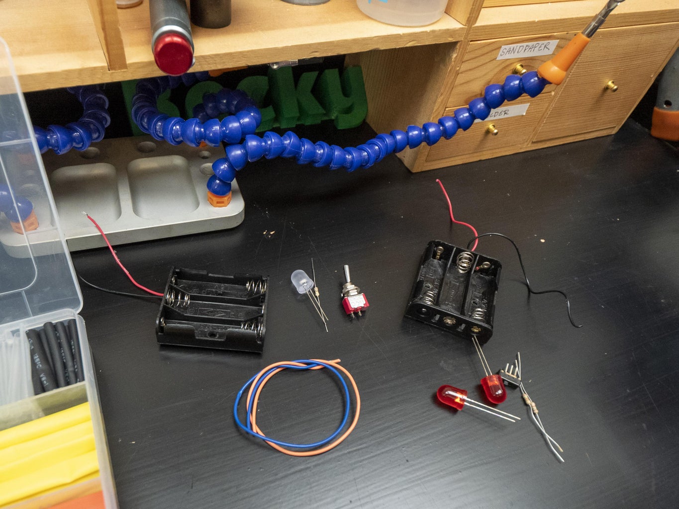
If you want to create a durable circuit, it's time to bust out that soldering iron. In addition to your LEDs, you'll also need resistors, some wire, some heat shrink tubing, a three-cell battery holder, either triple-A or double-A, and a switch, if your battery holder doesn't have one already.
Supplies
For this project, you will need:
- 3xAA or 3xAAA battery holder
- Switch (if your battery holder doesn't have one already)
- LEDs
- Resistors
- Heat shrink tubing
- Soldering iron
- Solder
- Wire strippers
- Flush cutters
- Helping hand tool
To keep up with what I'm working on, follow me on YouTube, Instagram, Twitter, Pinterest, and subscribe to my newsletter. As an Amazon Associate I earn from qualifying purchases you make using my affiliate links.
Step 1: A Single LED

The specs of the LED, resistor, and battery pack must all work in concert to power the LED enough to light it up, but not so much that it burns out.
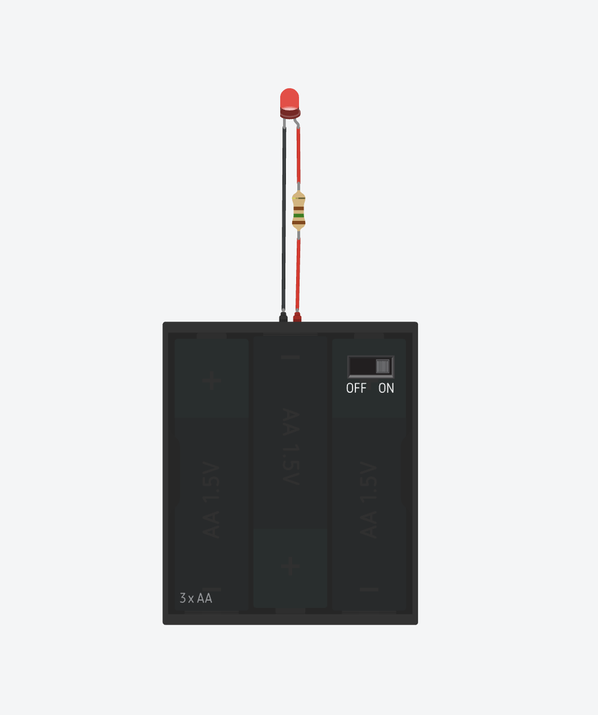
Here is a diagram of the basic circuit. Just as before, the LED positive side is connected to the battery's positive side, and likewise negative to negative. The current will flow from the battery through the resistor and LED and then back to the battery. The resistor and LED are connected in series, which means one after the other. In this way, the resistor limits the current flowing in the whole circuit, regardless of whether it comes before or after the LED in the circuit. And resistors aren't polarized like LEDs, so it doesn't matter which way round they go.
How do I calculate which resistor I'll need? Using Ohm's law (V=IR), we'll solve for R (R=V/I), using what we know about the LED and battery pack. On most sites that sell LEDs, you can find the datasheet and look up its forward voltage and forward current. A battery pack has its cells wired in series, which in this case adds each 1.5V cell together for a total of 4.5V. You can plug these values into one of the many online resistor calculators, or do it out by hand. for these standard 10mm LEDs and this 4.5V battery pack, any resistor value from 100 to 300 ohms will work fine. If you don't have the exact resistor, it's usually ok to go up to the next nearest common value. If the LEDs are all the same color you can compromise even further in the upwards direction, which will dim the LEDs just slightly.
Why doesn't the coincell LED circuit need a resistor? A coincell battery is already the correct voltage to power this LED, and it has enough internal resistance to prevent the LED from burning out. Coincell batteries contain lithium and should be recycled with e-waste, not thrown in the trash.
Step 2: Soldering the Single LED Circuit


To create the physical circuit, strip a bit of the insulation off ends of your battery holder's wires as well as both ends of two more wires of your desired length. Twist and tin the ends of the wires by adding a bit of solder. Tin both legs of the LED, all the way up near the plastic lens. Then fuse one wire to each of the LED legs by holding them together and reheating the solder so it flows between them. If you didn't add so much during tinning, you may need to add a bit more solder to get the best connection. If you use two different colors of wire, you can trim the legs of the LED shorter without forgetting which one is which. Add some heat shrink tubing to insulate the bits of exposed metal so they don't short out inside your project. If you only have one color of wire, you can label the wires with a piece of tape. Then add some more heat shrink tubing to cover the next set of joints. Since they won't have open ends, we need to remember to add the heat shrink tubing first.
Trim the resistor leads and solder it to either one of the LED wires. Then connect the battery pack wires, positive to positive and negative to negative. You'll need to add one more piece of heat shrink tubing to whichever battery wire ends up connecting to the other side of the resistor.
In case you also need to add a switch, it goes between the battery's power wire and the LED positive side.
Power up the circuit to confirm the LED lights up, and you're ready to put this in your next project.
Step 3: Multiple LEDs

Let's talk about adding more LEDs. It's easy, just duplicate the LED and resistor circuit and wire it in parallel with the first. That means both LED positives are connected directly to the battery's positive, and likewise both negatives to negatives. It's important that each LED have its own resistor to account for slight variations in the LEDs that prevent them from behaving exactly the same. A lot of folks think they can shortcut with one resistor for everything and it might work for a little while, but eventually, the circuit will fail. This method can work for upwards of 20 LEDs in parallel, but if it's your first time I recommend sticking to six or fewer and keeping all the LEDs the same color. If you want to mix and match different colors in the same circuit, you're going to have to get more precise about which resistors you use. Since they don't have the same internal resistance, the one that's easiest to flow through will get most or all of the juice.
Step 4: Soldering the Multiple LED Circuit


To assemble a circuit with multiple LEDs, you build the LED resistor assembly as before, but then join all the positive sides of the circuits together and the negative sides together before connecting the battery pack. Your resistors can live at the base of the wires branching out, or up next to the LED, or anywhere in between, so long as you provide suitable insulation to prevent the wires from shorting out if they get tangled.
Step 5: Enjoy!

I put my LED circuit in a plastic skull in preparation for Halloween. But you could put this circuit in a plush toy, in your cosplay props, or anything else that needs a little illumination. Let me know your plans and questions in the comments.
I hope to see you build one of these for your own purposes. I'd love to see your versions posted in the "I Made It" section below.
If you like this project, you may be interested in some of my others:
Thanks for following along! To keep up with what I'm working on, follow me on YouTube, Instagram, Twitter, Pinterest, and subscribe to my newsletter.

Participated in the
Back to Basics Contest

![Tim's Mechanical Spider Leg [LU9685-20CU]](https://content.instructables.com/FFB/5R4I/LVKZ6G6R/FFB5R4ILVKZ6G6R.png?auto=webp&crop=1.2%3A1&frame=1&width=306)


