

Introduction: Fiber Optic LED Lamp


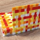
This LED lamp is in a way a continuation of my previous project "Fiber Optic and LEDs - a Wall Decoration", I think a natural one, I wanted to make something simpler, easier to do, that would be available to many of you. The "mechanical" parts of the lamp are 3D printed, the electronic part is simple and the plastic optical fiber is eye catching. The shape of the lamp is inspired by Helder Santos' project "Square LED Lamp" and the arrangement of the optical fibers is very similar to that of my project mentioned above. I will show you in this instructable how easy it is to make this LED lamp.
Step 1: Parts, Materials Needed…


- 3D printed pieces, files are on tinkercad;
- Side-glow plastic optical fiber 3 mm thick, about 5m;
- Addressable WS2812 LEDs (from a strip of 60 led/m) 32pcs;
- Arduino Mini Pro 5V microcontroller 1pc;
- Push button 12x12x7.3 mm 1pc;
- 5V power cable with DC plug 5.5x2.5mm 1pc;
- 5v/1A power supply with 5.5x2.5mm male plug 1pc;
And a few small things: wires, heat-shrinkable tubes for connections and hot glue.
If you are not used to tinkercad you have the stl files below:


Step 2: Electronic Schematics

Particularly simple as you can see in the graphic above
Step 3: Construction


I started with the 3D printing of the components, it takes quite a long time so in the meantime I was able to make the connections between the pieces of LED strip. It is good to check the correct operation of the LEDs before mounting the soldered pieces as in step3 of the project "Fiber Optic and LEDs - a Wall Decoration" (I just changed the value DATA PIN to 5 and NUM_LEDS to 32 in the test code).
After finishing the printing of the frame, the hardest part followed: ) fitting and fixing the four pieces of 8 LEDs each in the channels of the lamp frame. I loosened the protective plastic of the self-adhesive layer of the LEDstrip and for the best and most precise fixation I also used a few fiber optic ends inserted through the side holes. Then I slowly untied the protective layer and by pressing the strip to the frame, I fixed it. You can see the operation more clearly in the photos above.
This operation was followed by inserting in the side holes some pieces of plastic optical fiber. I cut the pieces as perpendicular as possible using the same template as in the "Fiber Optic and LEDs - a Wall Decoration" project. 8 pieces of fiber, so a total of 16 pieces, of different lengths join the pairs of holes that are at the same distance from the sides of the lamp frame, as in the photos above.
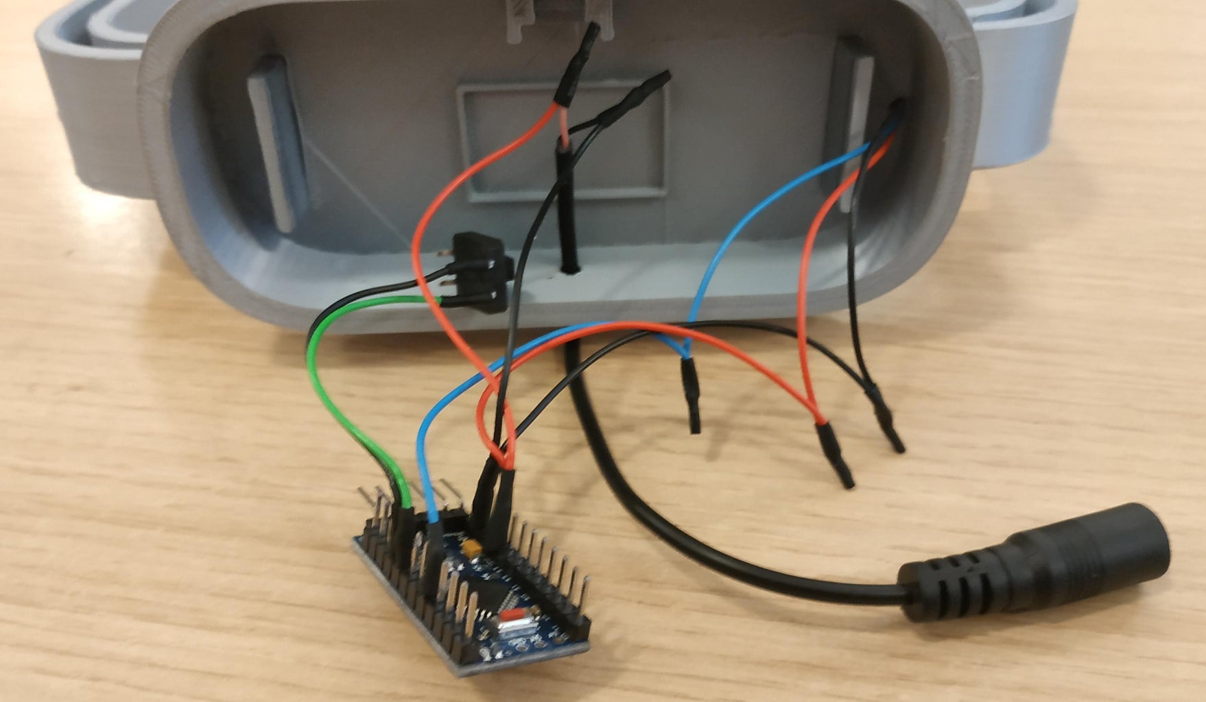
I made the rest of the connections according to the electronic schematics and then I mounted the lamp support and fixed it with a lot of hot glue, I fixed the touch button also with hot glue (not before mounting the push pin) and I fixed the Arduino Pro Mini module in the place provided by the support.
That's all!
Step 4: The Software


The final step in building the lamp was to upload the program to the Arduino micro controller. I used an USB to Serial module with the FT232RL chip connected as you can see in the photos above. Of course you can upload the code with other USB to Serial adapters. There are a lot of howto's online about programming the Arduino Pro Mini.
The source code of the program is on github, you can download it from there.
A few words about the program...
The lamp works in three main modes that can be selected by double-clicking on the push button: solid color mode (and with the breath effect), palette mode and effects mode. With a simple click in solid color mode you can choose different colors (9 colors) also with the breath effect, in palette mode you can choose several color palettes that are taken from PaletteKnife for FastLED and in effect mode…some effects :)
The program is essentially an adaptation of the codes from FastLED Breath for the breath effect, from palettes with button control for the different color palettes and the code from DemoReel100 with button for effects. For putting the Arduino Pro Mini to sleep, with a double click, I was inspired by this article. Also, at this moment (double click) the current operating mode is saved but also the settings from each operating mode.
External libraries I used (sleep.h and EEPROM.h are among Arduino's internal libraries) are FastLED and ArduinoMultiButton.
Step 5: Using the Lamp
In the video below you can see in more detail how the lamp can be used.
Step 6: Some Conclusions
I have to admit that I built this lamp for myself, I wanted to have something special :)
I put the lamp on the bedside table, I have been using it for a few days and I really like it. I am very satisfied with how the construction succeeded. However, maybe I will make some changes in the future…
For example in color palette mode I would make the brightness lower or choose color palettes with lower brightness. I would add a few more effects, I really liked the noise effect in my "Fiber Optic and LEDs - a Wall Decoration" project, I'm thinking of adding it to the effects mode. I could also power the LED strip through a MOSFET transistor as I did in my "Safety Armband" project and thus greatly reduce the idle consumption of the lamp. Now if I turn it off with a double click, the lamp consumes about 30 mA and in operation I measured a maximum of 400 mA.
I look forward to your reactions and questions as always.

First Prize in the
Anything Goes Contest

![Tim's Mechanical Spider Leg [LU9685-20CU]](https://content.instructables.com/FFB/5R4I/LVKZ6G6R/FFB5R4ILVKZ6G6R.png?auto=webp&crop=1.2%3A1&frame=1&width=306)


