

Introduction: DIY Power Supply


I recently stumbled across some pictures I took when I was building my first power supply, which I thought were lost, and so I've decided to make an instructable about it.
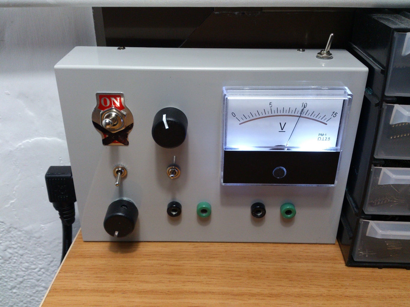
In this instructable I'm going to show how to build a fully adjustable PSU with dual output, this power supply is ideal for beginners as it is indispensable for powering many circuits with a wide variety of voltage inputs, it also can deliver enough current to power most of the circuits a hobbyist could build.
From my experience, this PSU isn't only easy to build, but it's also very reliable and tough, I've never had to change the regulators after all the abuse it has gone through, and this includes HV discharges, short circuits and many other crazy stuff that has destroyed ICs, mosfets, and many other electronic components. I'm really impressed with the performance of those regulators.
If you have checked my videos or my other instructables you'll see this is the power supply I normally use, and it's been working quite well even after all this time.
Step 1: How It Works
The design of this PSU is really simple, it is based around LM317 regulators, which are controlled using a resistor and a potentiometer, it basically acts like an operational amplifier, but instead of amplifying a signal, it decreases it's voltage, using a feedback loop to keep it constant.
For the input voltage source I've chosen a laptop charger, they are more compact than a transformer, and they deliver more current for the same space.
This PSU also has a double output, this means it has two independent regulators, this comes very handy when testing circuits that require various voltages. A switch on the top controls which voltage is displayed, since there is only one display.
Step 2: The Big List:
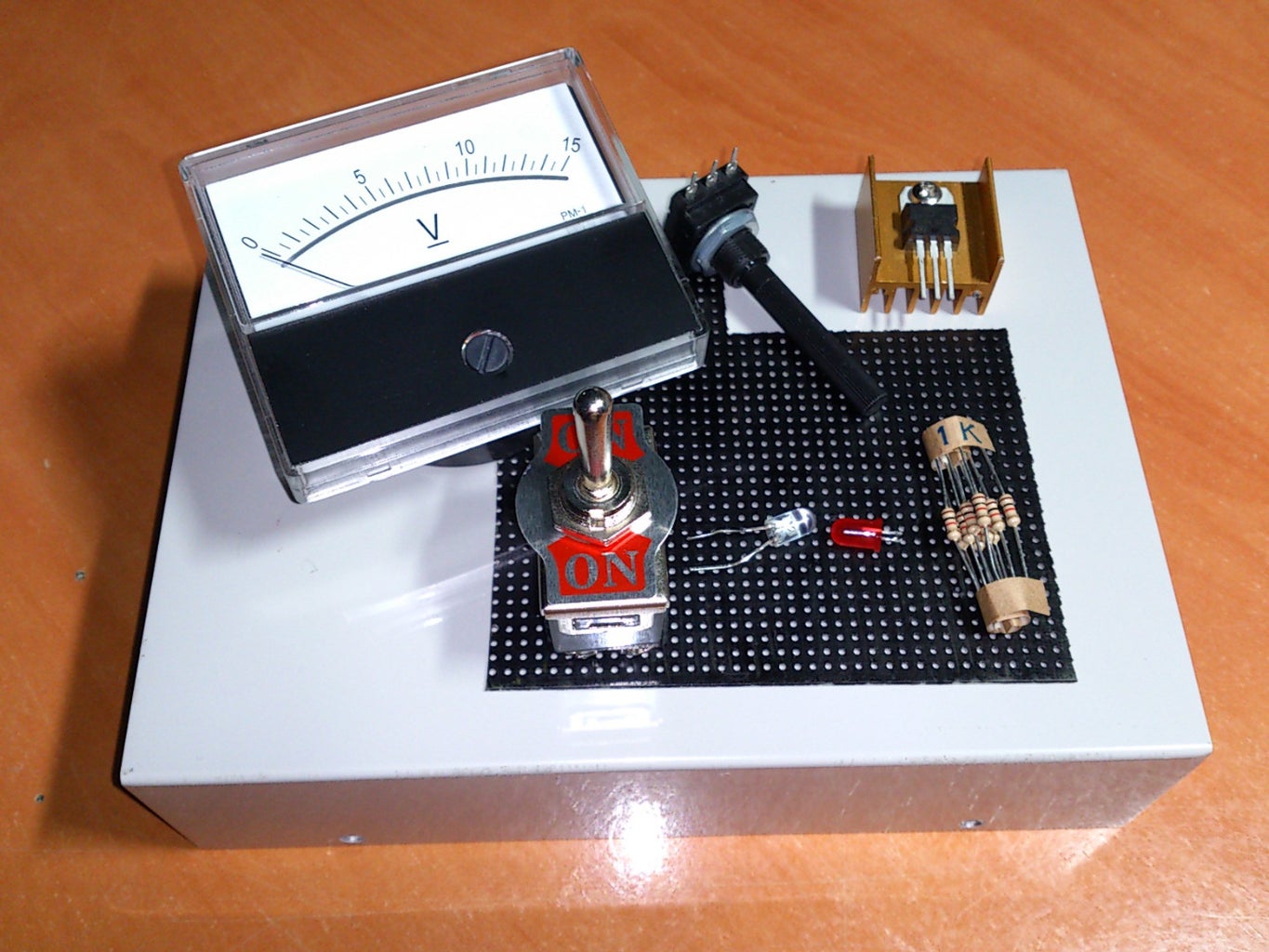
Materials:
- Laptop charger (Ideally with an output around 20V and >1A)
- 2x LM317 regulators (See note 1)
- Voltage display (See note 2)
- 2x Heatsinks (See note 3)
- 2x 4.7k potentiometers
- 2x pot knobs
- 4x Binding posts
- Resistors (You'll need to calculate their value, see step 6 for that)
- 3x Small switches ( Amp rating = or > than laptop charger amp output) (See note 4)
- 1x Big two pole switch (See notes 4 and 5)
- Perforated board, pcb... (See note 6)
- Some meters of Insulated copper wire with a decent diameter
- Shrink tube
- 230V connector (See note 7)
- A case big enough to fit all the components
Indispensable tools:
This tools are needed in order to complete the project, if you don't have them the build quality will be affected.
- Soldering iron
- Drill and circular file
Notes:
- If your laptop charger outputs more than 1.5 amps you can use more powerful regulators such as the LM338 (TO3 package), the LM317 is only capable of providing 1.5 amps, while the LM338 can deliver up to 5. You can also use a LM317+High power transistor (like a 3055) combination.
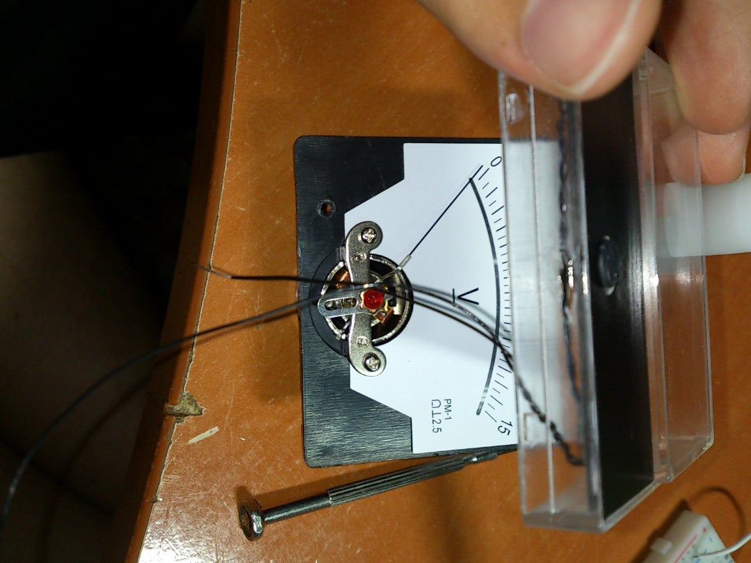
- You can use an analog or digital display, it doesn't matters, I used only one display with a switch to select the output voltage I want to display. You can also add current meters, I couldn't add them because of the space left. I'm also a bit skeptical about them as they are connected in series with the circuit and could affect it's behavior.
- You can't use the case as a heatsink, specially if it's metallic, since the LM317 regulator's output is also connected to the metal part of the package.
- Toggle switches are recommended since they are easier to mount on the case.
- The big toggle switch will only be used if you plan to make the AC mains grid switching inside the case.
- If you plan to use a PCB remember to increase the width or cover with solder those traces with higher currents flowing through them.
- The connector is not indispensable, it just helps to connect the internal circuitry with the AC mains, you could just pass a cable inside through a hole, but I guess the connector solution is more convenient.
Step 3: Capabilities
- Voltage: From 1.2 to ~40 volts output, never exceeding 40 volts input-output differential and always around 2-3 volts below the input voltage.
- Current: LM317: 1.5A , LM338: 5A (you can use the LM317+Transistor configuration for more current). Current may diminish with lower voltages since part of it is lost when regulating the voltage.
- Noise: (RMS) 10 Hz ≤ f ≤ 10 kHz 0.003Min 0.010Max %/VOut
Step 4: Selecting an Input Source
We begin by selecting a nice laptop charger, it has to be small enough to fit into the case, but it also needs to deliver an acceptable voltage and current, I used a small charger from a small laptop which was rated 19 volts and 2.1 amps, not much, but enough for powering most of the circuits I normally assemble.
You can also use a transformer with the typical bridge rectifier and capacitors, but this setup is very bulky and more expensive than reusing a laptop charger.
Step 5: Internal Design
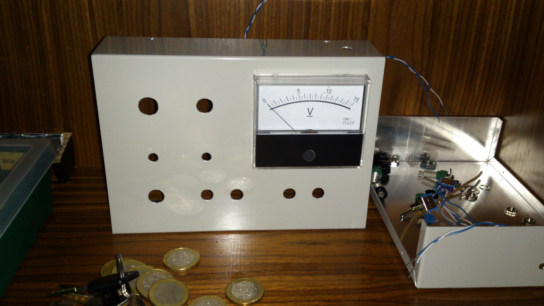
Once you have the charger it's a good time to start thinking where the components will be placed, in my case, space was quite limited, and so I needed to locate everything like a jigsaw puzzle to make everything fit.
It's quite useful to draw the components on the case to have a general idea of the space they use, you'll need to do this to calculate the length of the wires, since components like switches and potentiometers will need to be wired to the main circuit board to be mounted on the case. Always leave some margins so you can place the components even if you made some miscalculations.
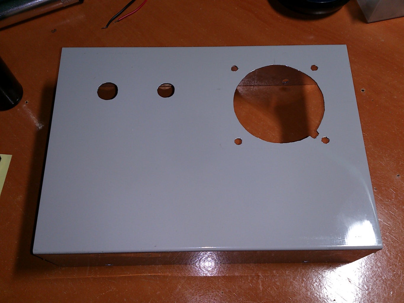
You can drill the holes now, just double check all the components can fit together. Make sure to use a nice separation and distribution of the components. I recommend using a carpenter's square and a ruler too keep everything aligned.
You might wonder why the pots so far apart and not in the same row, that's because the outputs of the right were intended to be DC, but for the ones on the left I wanted to make a square wave generator, and I finally abandoned the idea.
Step 6: Making the Circuit


Once it's all planned we can start making the circuit, which is quite straight forward.
I've divided the positive output of the charger in two, then I used two switches to control when the LM317s will be working. I also added a diode between the negative and positive output to prevent damage against overvoltages caused by inductive elements. You can add another diode between pins 3 and 2 for further protection.
To calculate R2 you can use the formula provided in the first picture, Vout will be the maximum voltage you want to output, but take into account the maximum output voltage will never be equal to the input voltage, there will always be a small voltage drop of around 2 volts, this value will depend on the current the regulator is supplying (see table).
The value of R1 is 4.7 kOhms, you can use other potentiometer values, but don't use very resistive ones to respect the minimum current flow indicated by the datasheet. If the current is too low noise could increase and the voltage adjustment operation would be negatively affected.
I recommend you test the circuit on a breadboard before assembling it onto the perfboard, remember to take into account the space for the heatsinks. Use plenty of shrink tube to avoid short circuits when everything is mounted together.
To connect the display (assuming you only want to use one) you should connect both outputs to side terminals of a three pin switch, the center or common terminal will be connected to the positive input of the voltmeter, and the negative to ground.
If you still have doubts you can watch this video about LM317 regulators, it was very helpful when I started using the LM317s.
Step 7: Setting All Up

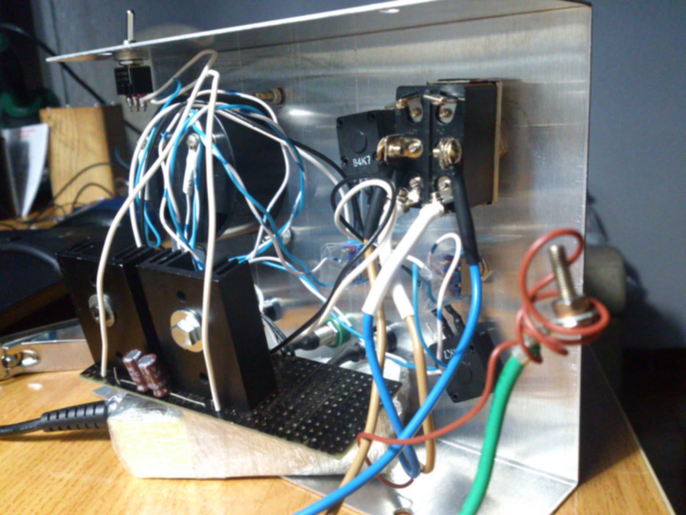


Next, screw in all the components, make sure there are no naked wires overlapping or hanging around. Use as many shrink tube as needed. You can also use zip ties to keep the wires in order.
WARNING:
If you plan to use a mains switch inside the case to control the laptop charger you have to be very cautious, don't do it by yourself if you're not familiar with electrical installations. If you're not sure about this, forget about the switch and connect the charger's plug directly to the grid.
Nothing can be left to chance. To make sure the wires don't fall off the screws I twisted the stranded wire around a small tube and then applied solder to make a rigid ring of wire, you can also use crimp rings (see picture). I also covered the back and sides of the case with a transparent plastic film just in case anything falls off.
If your house is grounded, connect the grounding cable coming out of the connector to the case
Remember to completely disconnect the charger when you're done if you don't plan to use any switch at all, chargers use energy whether they are being used or not. If you want to use a switch connect both poles of the charger to it, this will prevent any losses if the live wire remains connected to the charger.
Step 8: Extra Details:


I added some LEDs to illuminate the display, they also let me know if I've left the thing on.
To mount them I sanded them until they could sit flush over the plastic cover and then I glued them, the black strip is quite convenient since it hides all the wiring. I then connected the wires to a resistor and then to the positive output of the charger. You can calculate the value of the resistor by subtracting the LED forward drop voltages to the voltage of the charger and dividing everything by 0.02 (the current through the LEDs), in my case I should have used a 600 ohm resistor, but with a 1kOhm resistor the LEDs are bright enough.
If you are going to do this I recommend you use epoxi, I used cyanocrylate based glue (superglue), and it ended damaging the plastic. It seems this kind of glues are too aggressive against some kind of plastics.
You can also add a current limiter in series with the voltage regulator, they are useful if you want to test delicate circuits, by setting a current limit the circuit will be protected against overloads in case of failure, which might save your circuit from being fried. I didn't installed it since I don't think it's really necessary, I was also already running low on space.
Step 9: End
I hope you've been able to complete this projects, as always, thanks for watching.
If you have any questions or you want me to correct something don't hesitate to ask.

![Tim's Mechanical Spider Leg [LU9685-20CU]](https://content.instructables.com/FFB/5R4I/LVKZ6G6R/FFB5R4ILVKZ6G6R.png?auto=webp&crop=1.2%3A1&frame=1&width=306)


