

Introduction: Geek Clock: FiBiNo Fibonacci Binary Arduino Clock


I am a "lover" of watches and, when I saw "The Fibonacci Clock", I wanted to make one.
The "FiBiNo Clock" (Fibonacci Binary ArduiNo Clock) is a clock that displays the hours with Fibonacci method, while the minutes and the seconds with the Binary system and you have to be a geek to figure out what time it is.
To facilitate those who do not have time to waste on complicated binary, I also put a display that gives me the time and date.
As in my instructable I also added three buttons to adjust the time and date.
Step 1: Material


- Arduino/Genuino Mega 2560
- RTC DS1307
- 3 buttons
- 1 x LCD 16x2 I2c
- 1 x Stripboard
- multi-layer plywood panel 6 mm
- planed beech slats 10x10 mm
- 24 leds
- 12 Yellow
- 5 Red
- 3 Green
- 2 Blue
- 2 White
- resistances:
- 1 x 220Ω
- 1 x 370 Ω
- 6 x 10KΩ
- 17 x 470 Ω
- capacitors:
- 1 x 100 μf
- 1 x 0,1pF
- 1 x diode D4001
- 1 x voltage regulator L7805
- 1 x voltage regulator LM317
- 3 x transisor NPN BC547
- electric wires
- Dupont connector 2.54mm
- Female strip connectors 2,54mm
- screws M3
- dice m3
- semitransparent plexiglass
- Switch
- DC connector 2.1 / 5.5
- self-tapping screws
- glue
Step 2: Numb3rs Fibonacci - Binary

Fibonacci was an Italian mathematician who lived in the the XIII century in Pisa, to resolve a question of calculation (A mathematical law to describe the growth of a rabbit-breeding) has entered into a series of numbers, in fact the "Fibonacci sequence":
A sequence of positive integers in which each number is the sum of the two previous numbers.
1, 1, 2, 3, 5, 8, 13, 21, 34….
To calculate What time is it, just sum the numbers lit.
The binary number is a base-2 number system with only 0 and 1.
In a binary figure, each number has a value with an exponent that depends on the position in which it is located.
Starting from the first issue on the right, the exponent is 0, the second is 1, the third is 2, etc., In so doing, each LED assumes a fixed value which together to others, gives me the minutes and the seconds.
Position:
- 6 = 2⁵ = 32
- 5 = 2⁴ = 16
- 4 = 2³ = 8
- 3 = 2² = 4
- 2 = 2¹ = 2
- 1 = 2º = 1
Example:
•○ ○ • • • = 100111 = 1x2⁵ + 0x2⁴ + 0x2³ +1x2² + 1x2¹ + 1x2º = 32 + 0 + 0 + 4 + 2 + 1 = 39
As mentioned before...things to Geek
Step 3: Case


I'm not a good carpenter and I have not the appropriate equipment, but with what I had I made a case "artistic".
I used the plywood panel 6 mm and the laths 10 mm,for cutting I used for a metal cutting saw and an electric sander
I used to paste the "Loctite" quick-setting glue.
Dimensions (mm):
length 170; height 150; depth 100
To facilitate the assembly and the possible disassembly clock, I glued inside of the strips to create the grooves where to put the Arduino and the circuit board (step 4)
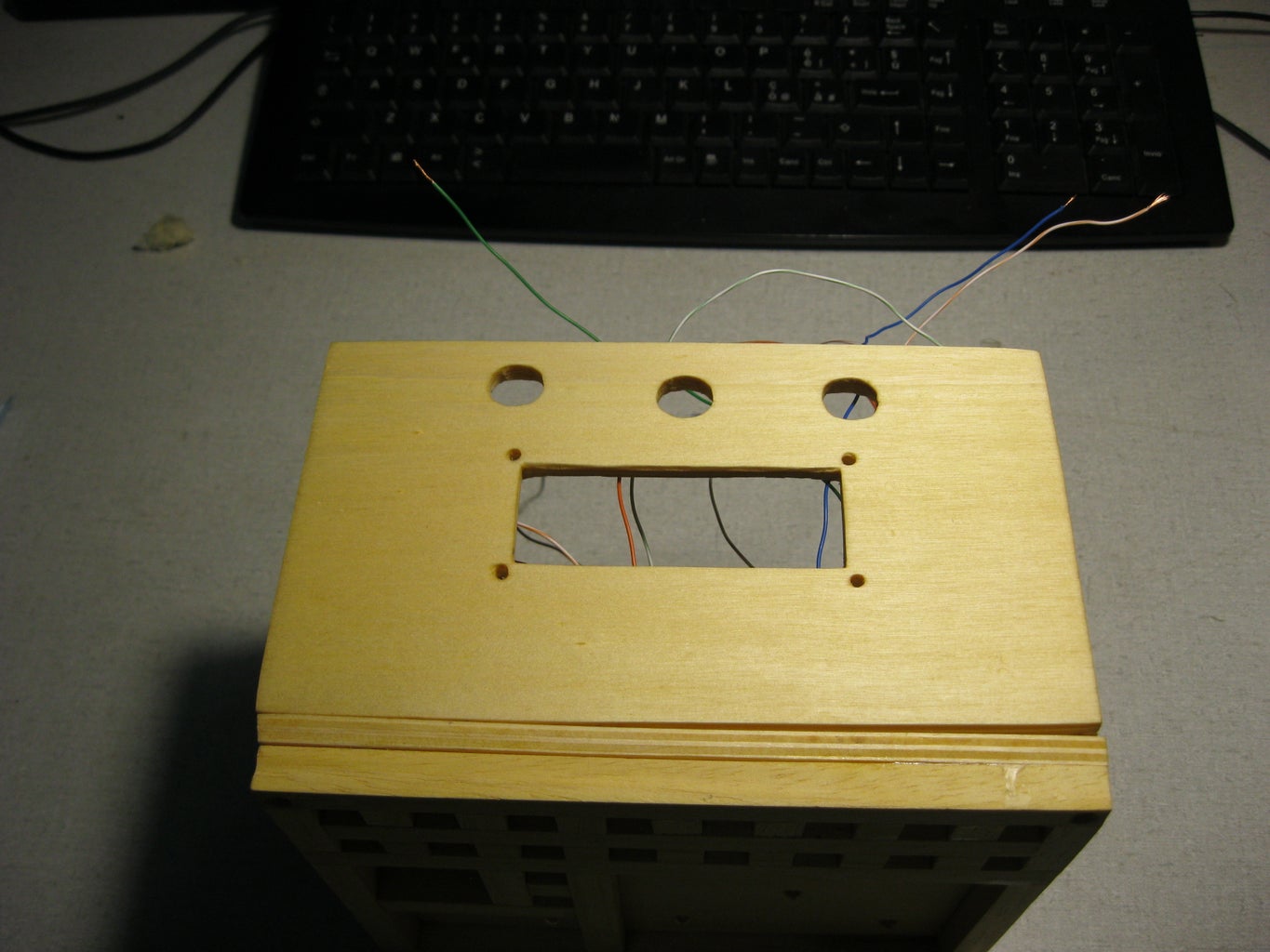
In the front panel must drill the holes for LED 5 mm, in the top panel the holes for the buttons (depending on the size of the button) and the groove for the LCD screen (this also depends on its size), in the right side panel, the slot for the Arduino USB socket, in the rear panel the holes for the switch and the power connector
Step 4: The Circuit Board


To facilitate links with arduino I realized a circuit with a "Stripboard"
The novice can also leave on breadboard but it seems a good reason to learn to weld (guide "how to")
As you can see, I added a voltage regulator (LM 317) which, together with the resistances R1 and R2, provides me 3.3 volts, in order to implement the project with other components (ESP8266)
Step 5: Electrical Assembly


Connect the cathode of all the LEDs to the ground.
Welded, to each anode, an electric wire connected with a Dupont female connector 2.54 mm.
Solder the wires to the buttons, connected with the connector and Dupont, very patiently, following the diagram, connect the wires to the board and then to the Arduino board.
It is preferable to use wires of various colors and leave long, doing so is easier mounting.
Before closing the Case, make sure everything works.
Step 6: Arduino Code

Link:
To view the time Fibonacci, the code is simple enough:
if (timeOra==1 || timeOra==13){ digitalWrite(hfib1a, HIGH);} if (timeOra==2 || timeOra==14){ digitalWrite(hfib2, HIGH);} ecc.
To display the time in a binary system, the method is a bit 'more complex:
- const byte numPinm = 6; //numbers pin minutes
- const byte numPins = 6; //numbers pin seconds
- byte pinm[] = {27, 28, 29, 30, 31, 32 };// pin binary minutes
- byte pins[] = {33, 34, 35, 36, 37, 38};// pin binary seconds
- for(int i = 0; i < numPins; i++) { pinMode(pins[i], OUTPUT); } // set the seconds pin as an output
- for(int i = 0; i < numPinm; i++) { pinMode(pinm[i], OUTPUT); } //set the minutes pin as an output
- String binNumber = String(timeSecond, BIN);//formats the seconds in binary
- int binLength = binNumber.length(); //stores the number
- if(timeSecond > 0) { for(int i = 0, x = 1; i < binLength; i++, x+=2)//for statement
- if(binNumber[i] == '0') state = LOW; //if the binary number is 0, the state is low
- if(binNumber[i] == '1') state = HIGH; //if the binary number is 1, the state is high
- digitalWrite(pins[i] + binLength- x, state); //bring the state to the corresponding LED
The same also applies to the minutes
Step 7: The Front Panel in a Semi Transparent Plexiglass

I used a purchased panel to Brico Center 0.3 mm thick
It was cut with a hacksaw and designed with a permanent marker (the ones to write the CDs).
Step 8: Final


Since too much like that of our friend, I preferred not to put the front panel.
The choice is yours whether to use.


