

Introduction: Homebrew 8-Bit Computer With TinyBASIC and ATMEGA1284P


I have assembled many desktop computers over the years but it's just not the same when you don't use a soldering iron! I wanted to build a computer from scratch for a long long time because I find when you have a go at building something go gain a better knowledge of it's inner workings. I have previously built homebrew computer variants using 6502 processors however these systems are not friendly for the novice or intermediate maker. I have also finally joined a hackspace (@NHackspace) so I wanted to put all my hacking skills to the test. This simple computer I built is based on an Arduino running TinyBASIC which has been done before but I wanted to do a complete build with homebuilt PCB, keyboard interface, monitor / tv output, sound and SD card storage. By day I am an industrial controls engineer and tend to use very robust proven modules in control systems rather than handmade parts. I build homebrew computers and electronics as a hobbyist and not a computer scientist or computer engineer so I am going to highlight all the "gotcha's! I came across doing this build.
I decide to base this 8-bit computer on the ATMEGA1284P-PU chip as it has a high spec for an Arduino compatible 8-bit micro controller, the basic specification is as follows:
SRAM - 16kB
Max Clock Speed = 20 Mhz
Pins = 40 DIP (32 Programmable I/O)
Flash Memory = 128kB
EEPROM = 4 kB
If you compare this chip to an Arduino Mega and Uno the standout feature is the SRAM. The Mega has 8kB of SRAM, 4kB of EEPROM and 256kB of Flash Memory whereas the Uno has 2kB of SRAM, 1kB of EEPROM and 32KB of Flash memory. This gives an 8-bit computer using the Atmega1284P a better chance of successfully running the TinyBASIC compiler.
One of the big "gotcha's" when using the Atmega1284 DIP is that it exists in two forms, the 1284p-pu and the 1284-pu. If you want to build this Instructable you will need the Atmega1284p-pu unless you want to spend hours finding the code in the Arduino Core files that needs to be changed....trust me I've been there!
Step 1: Tools, Consumables and Parts List

Although I have many of my own tools being part of a hackspace has made access to tools and equipment much easier and more importantly advice from the surrounding community on using them. I was quite new to 3D printing so the advice on this was very valuable.
The tools I used were:
- Soldering Iron
- 3D Printer - Ender 3 Pro
- Laser Cutter- Greyfin A2
- Bench drill and PCB drill bits
- Various hand tools such as pliers, cutters, screwdrivers, knives etc.
- Tubs to hold chemicals and water
- Safety equipment such as gloves goggles etc.. especially when drilling or etching using Ferric Chloride.
- Laptop with the following Software:
- Fusion360
- Ultimaker Cura
- Fritzing
The consumable materials I used were:
- Ferric Chloride
- Clean Water
- Detergent
- Solder
- Press-n-Peel Paper
- 3D Printer Filiment
- Wire wool
The components I used were:
- ATmega1284P-PU x 1
- Arduino Nano x 1
- 40 Pin PCB Socket x 1
- 15 Pin female header pins x 2
- 6 Pin female header pins x 2
- 2 Pin female header pins x 9
- 5V Voltage Regulator
- Jumper wires x 8
- SD Card Shield x 1
- 10 uF Capacitor x 2
- 16 MHz Crystal x 1
- 22pF Capacitor x 1
- PS2 Keyboard Socket x 1
- RCA TVoutput Socket x 1
- Piezo Buzzer x 1
- Blue LED in bezel x 1
- 9V Battery Holder x 1
- SPST Power Toggle Switch x1
- DPST Programme Toggle Switch x 1
- 1K Resistor x 1
- 470 ohm Resistor x 1
- 10k Resistor x 1
- 220 ohm Resistor x 1
Step 2: Motherboard


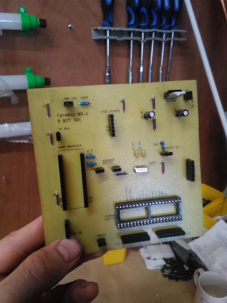


For this build I wanted to design and build the motherboard from scratch. Other members of the hackspace were quick to point out that it would probably be more cost effective to order a PCB online. This was definitely true however the project was to homebrew a computer so I went for it. I designed the pcb using Fritzing and built a pre-prototype on a solderless breadboard before etching the board. One of the "gotcha's" from this experience is that building circuits with higher speed oscillators don't always work perfectly on solderless breadboards, I found the PS2 keyboard didn't work well however it was good enough for a proof of concept. The pcb layout is so simple it is probably easier to read than a schematic.
I used the toner transfer method for etching the PCB, I found using Press-n-Peel transfer paper worked best for me. The process I used for making the PCB was as follows:
- From Fritzing, Print a negative image of the PCB traces using a laser printer onto the Press-n-Peel paper. Although I printed at a 1 to 1 scaling this didn't quite work out exactly when I placed a 40 pin chip on the print. I had to increase the print size by 2% to get the exact size.
- Cut the copper clad board to size, I simply used a fine hacksaw for this and cleaned up the edges with a file.
- Clean the copper board using wire wool then warm soapy water.
- Cut out the Press-n-Peel print to the PCB size and place trace side down on the copper.
- Cut out a piece of plain paper 1" bigger than the PCB and wrap it over the Press-n-Peel and tape onto the uncoated side of the board. This holds everything together and stops the Press-n-Peel overheating.
- Turn on domestic Iron to about 3/4 setting - this worked for me but depends on the iron.
- Prepare a container containing about 25mm of cold water.
- Iron on Press-n-Peel evenly for about 4 minutes - again this really dependant on the iron and pressure you are applying.
- Put the PCB into the cold water to cool.
- Remove the plain paper and peel off the Press-n-Peel, this will leave the blue traces.
- Put about 40mm of Ferric Chloride in a container.
- Place the PCB in the Ferric Chloride.
- Use some tweezers or pliers and agitate the PCB in the Ferric Chloride until the exposed copper is dissolved, this takes about 10 minutes.
- Remove the PCB and Wash off the Ferric Chloride using clean cold water.
- Remove the remaining Press-n-Peel with wire wool and clean the PCB again.
- Inspect the PCB and repair any traces using a PCB pen, I only touched up a couple of traces.
When Ironing on the Press-n-Peel transfer onto the copper you need to heat the board evenly, with a PCB this big (bigger than the Iron) it's not easy and it may take some trial and error.
After the copper side of the PCB was complete I made a sort of "silk screen" using conventional transfers printed using a laser printer. Having the silk screen made populating the board with components easier.
The above steps left me with a blank PCB ready to drill. People seem to be worried about drilling PCB's thinking it is time consuming and difficult however I did not find this the case at all. I drilled the PCB with a standard bench drill using. Specialist PCB drill bits have the advantage of having a larger shank which keeps them stable in the drill chuck. I drilled the PCB with 1mm through holes. I took my time and the drilling process took about 1 hour.
With the PCB manufactured I simply had to solder all the components in place.
Step 3: Enclosure


The enclosure build was very fun and used many of the skills and resources available in a hackspace. The enclosure itself comprises of a laser cut 3mm wedge shaped plywood box with laser cut acrylic base and hinged lid so that the PCB can be viewed. The top platform of the enclosure was manufactured from sheet aluminium bent using a sheet metal brake.
The PCB is mounted on a 3D Printed bracket manufactured from PLA. This was designed using Autodesk Fusion360 and then sliced using Cura before being printed on an Ender 3 Pro. This print took quite along time, about 4 hours. The same process was done to make a bracket for the SD card shield. I found Fusion 360 pretty user friendly as I had used Autodesk Inventor professionally in the past and it has a similar feel. My 9-year old son is fascinated by 3D printing so he has dived straight into Fusion 360, he thinks of it like playing Minecraft!
15mm x 15mm aluminium extrusions were utilised to hold the enclosure together.
Step 4: Software

The software is quite a challenging area of this build, especially if you are a novice, if you have not drilled down into this level of detail before don't panic and stick at it, you will get there! I wanted to run a BASIC compiler on this 8-bit computer and having built other homebrew computers in the past I wanted to keep it simple enough for most people to achieve without entering the realms of eeprom programmers and binary files. Having looked at other projects using Arduino to run a TinyBASIC compiler this looked like a great option. TinyBASIC is a slimmed down version of BASIC which has been adapted for Arduino. The sequence of events I took for getting software onto the chip was as follows:
Getting Software on the ATmega1284p
- Download Mighty 1284P: An Arduino core for the ATmega1284P.
- Making sure the Arduino IDE is closed and install the Mighty-1284p folder in the hardware folder in your Arduino folder then restart the Arduino IDE.
- Build a simple bootloader circuit on a solderless breadboard connected to an Arduino Uno.
- Upload bootloader sketch.
- Convert bootloader breadboard to a "bare bones" Arduino with FTDI connected and upload blink sketch to test the Atmega1284p.
- Download TinyBASIC Plus and open in your Arduino IDE.
- With the FDTI connected download TinyBASIC Plus to the ATmega1284p. At this point don't change any settings in the TinyBASIC.
- At this point you should be able to try out TinyBASIC in the Serial Monitor on you laptop or computer. Try a simple program such as:
- 10 print "Hello, world"
- 20 goto 10
- run
- At this point you can now modify the TinyBASIC sketch so that the computer can use the PS2 keyboard, SD Card reader / writer and piezo sound output.
An Arduino core is the place where all built-in functions source files can be found, a link to the JChristensen Arduino core I used is here. https://github.com/JChristensen/mighty-1284p/tree/v1.6.3
The Arduino ISP is an In-System-Programmer that is used to program AVR microcontrollers. You can use the Arduino ISP to upload sketches directly to Arduino boards. In this occasion the ISP is being simple used to upload a bootloader using the Arduino Uno as an interface. A great link for instructions on how to upload the bootloader and test it is here together with instructions on how to connect an FTDI. Technoblogy.com - using the ATmega1284 with the Arduino IDE. Be careful when using the FTDI as you need to check you have the correct driver installed, a "gotcha" to be careful of!
I recommend using the latest version of TinyBASIC Plus as another "gotcha" I found was that when using one of the older versions the input function would not work with an external keyboard. A link to download TinyBASIC Plus is here https://github.com/BleuLlama/TinyBasicPlus.
Modifying TinyBASIC Plus
To get the functionality out of TinyBASIC plus you need to modify many sections of code, below are code snippets of the sections of code and the starting line number to help find the code to modify, this mght change as the TinyBASIC code gets updated so these line numbers are only a guide. I copied the code into notepad++ and used the search function to hunt out the code to modify. I have shown these modifications in order.
First add the keyboard library to sketch and define the data and interrupt pins as shown below (starting at line number 135).
////////////////////////////////////////////////////////////////////////////////
// Keyboard support
#include <PS2Keyboard.h>
const int dataPin = 11;
const int irqPin = 10;
PS2Keyboard kb;
////////////////////////////////////////////////////////////////////////////////<br>
Enable the SD card by changing the code as follows (starting at line number 161).
// This enables LOAD, SAVE, FILES commands through the Arduino SD Library<br>// it adds 9k of usage as well.
#define ENABLE_FILEIO 1
//#undef ENABLE_FILEIO
Enable the Piezo output and define the pin it is to be connected to (starting at line number 181).
// this will enable the "TONE", "NOTONE" command using a piezo<br>// element on the specified pin.  Wire the red/positive/piezo to the kPiezoPin,
// and the black/negative/metal disc to ground.
// it adds 1.5k of usage as well.
#define ENABLE_TONES 1
//#undef ENABLE_TONES
#define kPiezoPin 15
Define the Chip Select pin for the SD card, sometimes called CS or SS (starting at line number 243).
// set this to the card select for your Arduino SD shield<br>    //#define kSD_CS 10
    #define kSD_CS 4
Setup RAM buffer size for program and user input (starting at line number 268).
#define kRamSize (RAMEND - 2768 - kRamFileIO - kRamTones)
Start up Keyboard (starting at line number 2070)
#ifdef ARDUINO<br>  kb.begin(dataPin, irqPin);
  Serial.begin(kConsoleBaud);	// opens serial port
  while( !Serial ); // for Leonardo
Read the keyboard (starting at line number 2114)
if(kb.available())<br> return kb.read() == CTRLC;
Read the keyboard again (starting at line number 2163)
if(kb.available())<br> return kb.read();
As we defined pin 4 for CS for the SD card it needs to be declared as an output. Another "gotcha" is that if you don't change these pins then there is a conflict with the pins used by the keyboard.
// due to the way the SD Library works, pin 10 always needs to be <br>  // an output, even when your shield uses another line for CS
  //pinMode(10, OUTPUT); // change this to 53 on a mega
  pinMode(4, OUTPUT); // change this to 53 on a mega
Display Output
The Arduino Nano mounted on the PCB handles the display output. The Arduino Nano TVout_Serial_Print sketch simply reads the serial port and if any data is available, it prints it out to a connected TV or compatible display using the TVout library. The hardware_setup.h library referenced in the TVout.h lirary defines the video and sync pins, pin 7 for video and pin 9 for video when using the Arduino Nano. These pins differ for other MCU's and could be changed by changing the hardware_setup.h file.
FTDI Header
The PCB is fitted with female header pins to connect an FTDI, this enables new firmware to be flashed to the ATmega1284P without removing any components. because the Nano is also connected to the same serial connection it must be disconnected before new firmware is flashed to the ATmega1284p. To enable this the system is fitted with a double pole toggle switch the "programme switch" which is put into the off position to allow the flashing of new firmware.
Step 5: Final Testing and Improvements
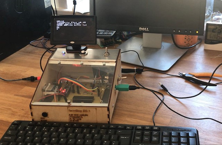
When all the components were built and inspected the complete system was finally assembled and tested. To test the system i wrote a few programmes in BASIC. A good test programme was a programme I wrote to find all the Prime Numbers up to a value inputted by the user. This is a great little programme for testing the performance of the computer. It is slightly more challenging than a normal because TinyBASIC has such a reduced instruction set. It has no "mod" which is a function that gives you the remainder when dividing two numbers. This is very useful for finding Primes, in our case it just took a bit more maths. I found it took about 5 minutes to calculate all the Primes up to 1000. This little programme was ported to several other retro computers in the hackspace and the race was on!
Another programme was a a simple tune to test out the Piezo buzzer and tone function. This was good fun and surprisingly good. I have included the Basic programmes I have written for others to try.
The biggest improvement I would make would be to the power supply. When testing the project I used a mobile phone power bank which provided no problems at all. When I moved to my bench top power supply I had problems which I suspect were caused by AC ripple. This was a big "gotcha" and easily solved by using a 9v battery as the power source. Although the power supply stage has two reservoir capacitors to help remove AC ripple, I think it would also be useful to include a low pass filter stage to remove any remaining AC ripple and improve the stabilisation of the DC output voltage under load conditions. I would also add 0.1uF decoupling capacitors to the power input on the Arduino Nano and ATmega1284p. A decoupling is there to supress high-frequency noise in power supply signals.
Note: It's called the farmBoy B0.1 because it was built my workshop in rural Norfolk, England, which was formally a barn used for raising cattle.
The code for the primes test programme is below.
10 PRINT "Tell me your prime number limit"
20 INPUT X
30 Y=1
40 FOR M=2 TO X
50 FOR P=2 TO M-1
60 Z= M- ((M/P)*P)
70 IF Z=0 B=B+1
80 NEXT P
90 if m=2 PRINT "1", " : ", "prime number:", "2"
100 IF B=0 Y=Y+1
110 IF B=0 PRINT Y, " : ", "prime number:", M
120 B=0
130 NEXT M


