

Introduction: How to Build Gripper Arm Tracked Robot Controlled Via Nrf24l01 Arduino


The instruction "How to Build Gripper arm Tracked Robot Controlled Via Nrf24l01 Arduino" will explain how to build a three degree of freedom gripper arm installed on tracked wheeler driven by dual motor drive L298N module using MEGA2560 Arduino controller.The gripper arm and robot movement will be remoted by 8-channel transmitter(see instruction "How to Build 8 Channel Transmitter Nrf24l01 Arduino"
Step 1: Materials & Tools


Materials
1. 1 - Arduino controller - MEGA2560
2. 1 - NRF24L01 module
3. 1 - Socket adapter for NRF24L01(For protect & stabilize NRF24L01 module)
4. 1 - LED 10 mm.
5. 1 - Resistor 1 kOhm. 1/4 watt.(Option)
6. 1 - Capacitor 0.1 microF /50V.
7. 1 - Capacitor 1 microF /50V.
8. 1 - Capacitor 100 microF /50V.
9. 1 - Diode 1N4007
10. 1 - 7805 IC Regulator 5V.
11. Dupont wires.
12. Female pin header
13. Male pin header
14.1 - Dual motor drive L298N module
15. Male JST Battery Pigtail
16. Heat shrink tube 1.5 - 10 mm.
17. Velcro tape
18. 1 - PCB.DIY. circuit board
19. Battery Lipo 11.1V. 2200 mAh (3 cells)
20. Tracked wheel toy with dual motors
21. Electrical 26 AWG wires
22. Acrylic sheet 5 mm. thickness
23. Bolts M3
24. Nuts M3
25. Tapered head self-tapping screw
26. 1 - Three degree of freedom gripper arm
27. Dean plug
Tools
1. Soldering gun
2. Soldering wire
3. Soldering paste
4. Screw driver
5. Plier
6. Hot glue gun
7. Epoxy glue
8. Two sides glue tape
9. Plastic cutter
10. Electrical drill
11. Hack saw
Step 2: Parts Installation & DIY PCB


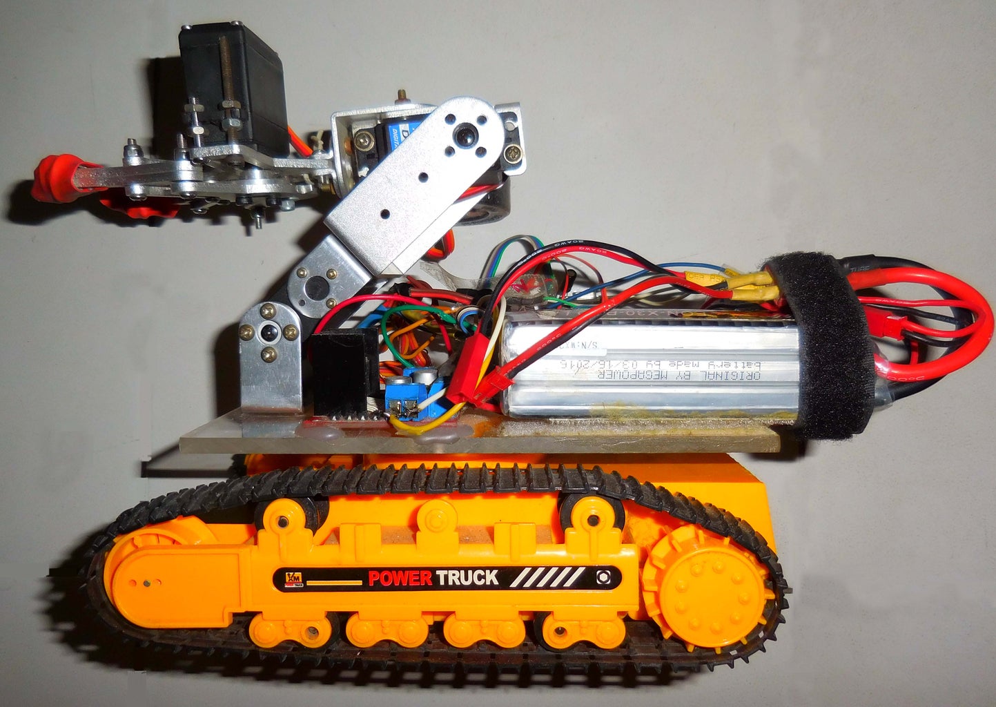
Mechanical parts installation
1.Cut and drill acrylic sheet to make platform base for equipments installation.(As your own design)
2.Fix acrylic sheet on tracked wheeler by self-tapping screws.
3.Fix gripper arm on base by M3 bolts and nuts.
4.Install L298N module on base by two-side glue tape.
5.Glue and paste velcro on acrylic base and battery.
Electronic parts installation
1.Making DIY PCB and wiring,soldering as above circuit diagram.
MEGA2560 pins to nrf24l01 module :
GND - GND
3.3V. - Vcc
9 - CE
53 - CSN
52 - SCK
51 - MOSI
50 - MISO
2 - IRQ
MEGA2560 pins to L298N module :
3 - ENA
4 - IN1
5 - IN2
6 - IN3
7 - IN4
8 - ENB
MEGA2560 pins to three servoes of gripper arm :
11 - Arm1
12 - Arm2
13 - Gripper
6.Assembly PCB on MEGA2560,putting pins on the correct headers as circuit diagram.
7.Wiring and connecting three servoes of gripper arm to PCB.
8.Attach MEGA2560 board on acrylic base by two-side glue tape.
9.Wiring dual motors to L298N module.
10.Checking and finding short circuit points.(beware of high current electrical short circuit ,will caught fire)
11.Testing the direction of motors and gripper arm servoes.

![Tim's Mechanical Spider Leg [LU9685-20CU]](https://content.instructables.com/FFB/5R4I/LVKZ6G6R/FFB5R4ILVKZ6G6R.png?auto=webp&crop=1.2%3A1&frame=1&width=306)


