

Introduction: How to Control Tracked Robot Via Joystick NRF24L01 Module Arduino Part2 Rx


The instruction "How to control Tracked Robot via Joystick NRF24L01 Module Arduino Part2 Rx" will describe the method how to build Receiver(Rx) on Tracked Robot for Transmitter(Tx) in the instruction "How to control Tracked Robot via Joystick NRF24L01 Module Arduino Part1 Tx".
Thanks to arduino-info.wikispaces.com , github.com/maniacbug/RF24 for RF24 library and other nRF24L01 module information.
You can purchase electronic parts from Aliexpress, Banggod,Ebay,etc.
Project more : http://hobbywitch666.blogspot.com
Step 1: Materials & Tools


Materials
1. 1 - Arduino controller - Nano
2. 1 - NRF24L01 module
3. 1 - Socket adapter for NRF24L01(For protect & stabilize NRF24L01 module)
4. 1 - LED 5 mm.
5. 1 - Resistor 1 kOhm. 1/4 watt.
6. 1 - Capacitor 0.1 microF /50V.
7. 1 - Capacitor 1 microF /50V.
8. 1 - Capacitor 100 microF /50V.
9. 1 - Diode 1N4001
10. 1 - 7805 IC Regulator 5V.
11. Dupont wires.
12. Female pin header
13. 1 - L298N Arduino module
14. Electrical wires
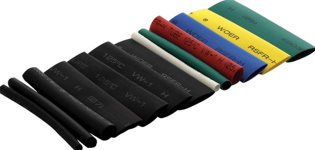
15.Heat shrink tube 1.5 - 10 mm.
16. PCB - DIY circuit board
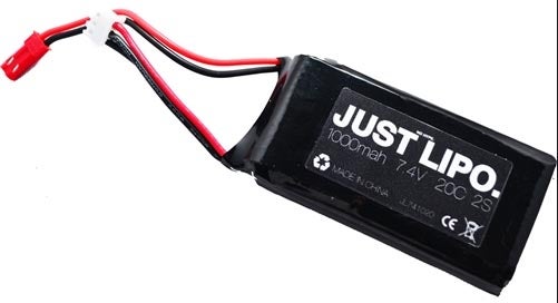
17. Battery Lipo 7.4 V. 500-1000 mAh
18. Velcro tape
19. Tamiya track and wheel set
20. Tamiya dual geared box
21. Tamiya plastic perforated plate
22. 2 - pairs of JST plug
Tools
1. Soldering gun.
2. Soldering wire.
3. Soldering paste.
4. Screw driver.
5. Plier.
6. Hot glue gun.
7. Miscellaneous screws ,bolts and nuts.
Step 2: Electronic Parts & DIY PCB Installation


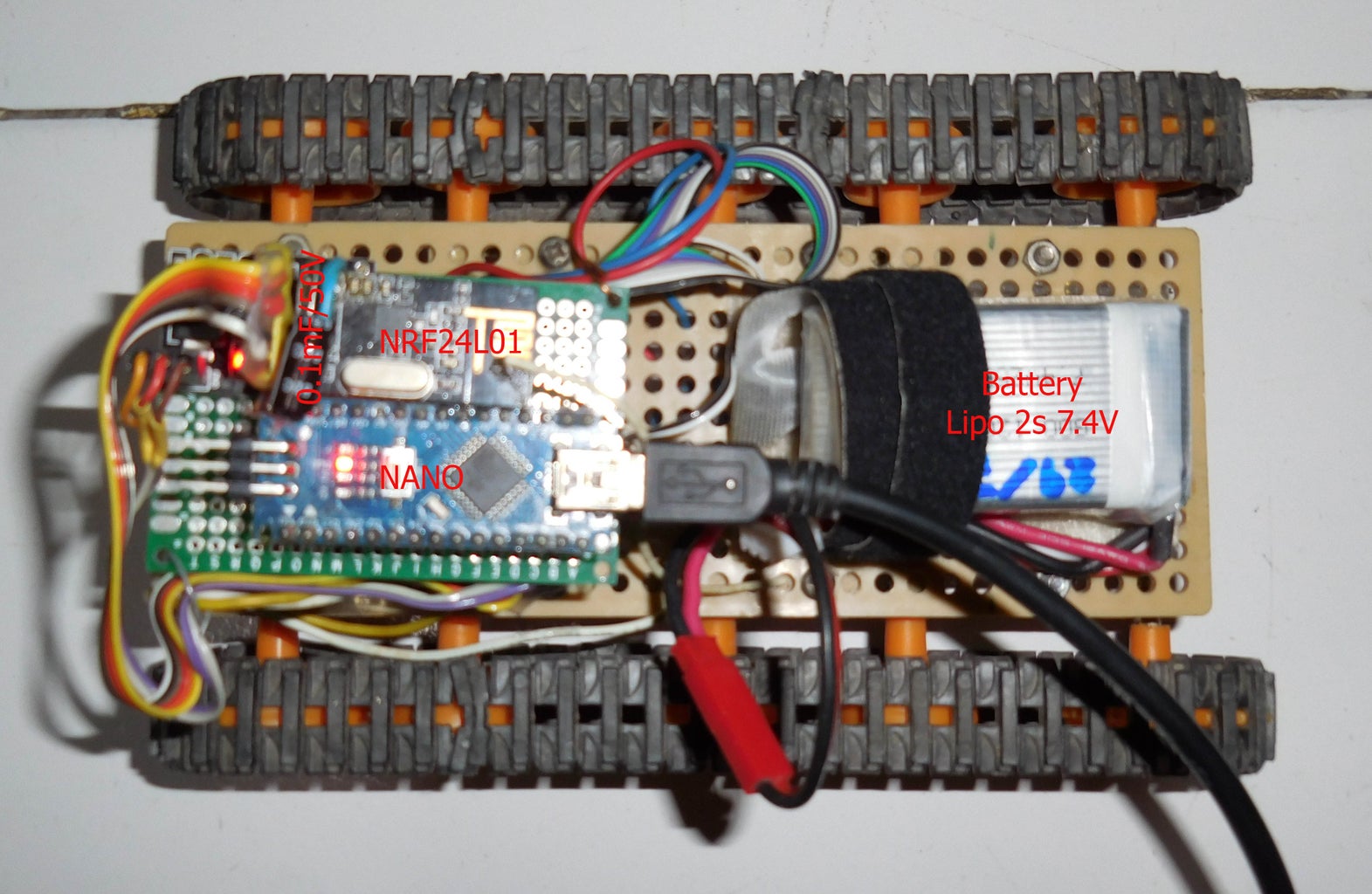

DIY PCB Building
Connecting electronic parts on PCB according to circuit diagram and solder them.
Arduino Nano pin to L298N
Pin No :
3 - ENA
4 - IN1
5 - IN2
6 - ENB
7 - IN3
8 - IN4
GND - GND of L298N
L298N module
Vcc - Battery positive pole
GND - Battery negative pole - GND of NANO
MotorA - Left motor
MotorB - Right motor
nRF24L01 module Socket Adaptor to Arduino Nano
Pin No :
Vcc - 5 V. supply (Do not connect 5V. directly to nRF24L01 module,it's supplied only 3.3V.)
GND - GND
CE - 9
CSN - 10
SCK - 13
MO - 11
MI - 12
IRQ - 2
*If you have communication problem,you can change connection from pin 13,11,12 to pin SCK,MOSI,MISO of Nano programming pins.
*It's necessary to add 0.1 microF to nRF24L01 module pin Vcc/GND because the module needs stable current and voltage.
Step 3: Software Installation
Arduino sketch and Library :
1.Down load attached sketch file .ino and download library zip file for nRF24L01 module from https://github.com/maniacbug/RF24/downloads
2.Add library zip file to Arduino software.You will see new library RF24-master in Examples menu.
3.Before using new nRF24L01 modules,we shall burn the modules by uploading default sketch pingpair and GettingStarted for tuning up frequency otherwise it will has uncommunication problem.(Use another Arduino Nano and nRF24L01 modules for pairing)
4.After success matching the frequency ,we can comply and upload attached Rx sketch to NANO controller.
(If you have problem,go to visit website https://arduino-info.wikispaces.com/Nrf24L01-2.4G... for more information)
5.Test Receiver(Rx) with Transmitter(Tx).See serial monitor showing the print out data as attached video clip.


![Tim's Mechanical Spider Leg [LU9685-20CU]](https://content.instructables.com/FFB/5R4I/LVKZ6G6R/FFB5R4ILVKZ6G6R.png?auto=webp&crop=1.2%3A1&frame=1&width=306)


