

Introduction: How to Make a Vibration Sensor


While browsing Instructables I came across teebee918's project where he made 2 different types of "motion" sensors. I continued on the principle of one of the sensors. This sensor consists of a spring on which an iron ball is mounted. When this ball moves it hits a conductive ring around the ball, causing the sensor to make contact.
The contact time of this sensor is very short. Connecting a lamp or alarm to it to be alerted when the sensor moves is therefore difficult. By connecting a simple circuit with an IC555 timer as a basis (as in the Touch on Touch off Instructable) this issue solves. When the sensor registers movement, the output becomes active. The output must be reset with a reset button.
The combination of these 2 projects makes a complete sensor. You can use a vibration sensor for various applications. They are used, among other things, for detecting wear on engines. This sensor is not that precise and is nice for hobby purposes or simple projects.
Video tutorial
Supplies
- 555 timer
- Tactile switch
- LED (any color)
- 330 Ohm resistor
- 9V battery
- 9V battery clip
- Spring (from a pen)
- Iron ball (from ball bearing)
Step 1: 555 Timer


In this project I am going to manually control the "flip flop" circuit in the 555 timer. The "vibration sensor" turns on the flip flop circuit causing the output to go high and the LED to light, the push button resets the flip flop circuit causing the output to drop and the LED to turn off.
To keep it clear, I have added an image of the 555 timer schematic operation and pin assignment. Also a simple wiring diagram.
Step 2: Connect the LED


To visualize whether the output of the 555 timer is high, I mounted an LED. The timer output is pin 3, which gives a positive voltage when high. The LED will be between pin 3 and pin 1 (GND).
To protect the LED there is of course a resistor in between. In principle, it does not matter in front of or behind the LED, but because there will be connections to the GND later in this project, I have chosen to attach it directly to pin 3.
Solder the 330 Ohm resistor to pin 3. Then mount the LED between pin 3 and 1, with the anode (+) to pin 3 and the Cathode (-) to pin 1.
Step 3: The Reset Button


To reset the flip flop circuit in the 555 timer, a tactile switch is placed between pin 5 and 6. When this switch is pressed, control voltage is applied to the threshold connection, causing the internal flip flop circuit to reset.
Solder the tactile switch between pin 5 and 6.
Step 4: Install the Spring


To enable the internal flip flop circuit in the 555 timer, connect the trigger connection (pin 2) to the GND (pin 1) connection. The vibration sensor part is attached to these 2 pins.
To start, mount the iron ball to the spring by soldering it to it. I chose soldering because with gluing it is not certain whether the spring and the ball touch each other and therefore it is not certain whether they conduct.
Now solder the other side of the spring to pin 2. Make sure that the spring is as straight up as possible.
The first part of the vibration sensor is ready, I will show the other part in the next step.
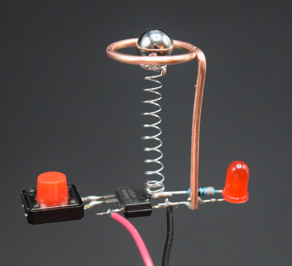
Step 5: The Ring


A ring of conductive material is placed around the ball. I have opted for I chose a piece of copper wire that I still had lying around here. I made the rounding by twisting it around a round object (solder tin holder). You can of course also use a marker or something similar for this.
Place the ring around the ball and connect it with the GND connection (pin 1).
The vibration sensor part is now ready. When you shake the sensor, the ball hits the ring and the 555 timer switches on the output.
Step 6: Allmost Ready


The sensor is almost ready. Only the power supply has to be mounted. This is of course possible with a variable power supply, but I opted for a 9V battery.
Mount the red cable from the battery clip to pin 8 (+ Vcc) of the 555 timer.
Mount the black cable from the battery clip to pin 1 (GND).
Step 7: Ready


Ready! Connect the 9 volt battery and the circuit can be tested. shake the device turns the LED on, the tactile button turns the LED off. Remember a simple circuit has been added as an image to make it even clearer.
The 555 timer is very fragile. When soldering, make sure you don't let it get too hot, it can break it.
Video tutorial
I hope you liked this Instructable and it helps you understand the 555 timer. It has made a lot of sense to me and I plan to do more projects with it because it has so many possibilities.

Participated in the
Make it Glow Contest


