

Introduction: How to Make an Accurate Air Flow Rate Sensor With Arduino for Under £20 COVID-19 Ventilator


Please see this report for most recent design of this orifice flow sensor: https://drive.google.com/file/d/1TB7rhnxQ6q6C1cNb...
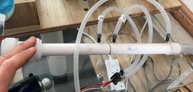
This instructables shows how to build an air flow rate sensor using a low cost differential pressure sensor and readily available materials. The design is for an orifice type flow sensor, the orifice (in our case a washer) provides a restriction and we can calculate the flow by measuring the pressure difference across the orifice.
Originally we designed and build this sensor for our project called OpenVent-Bristol which is an open source design of rapid manufacture ventilator for treatment of COVID-19. However this sensor can be used in just about any air flow sensing application.
This initial version of our design is made entirely using off-the-shelf parts, no 3D printing or laser cutting is needed.
The attached drawing shows a cross section drawing of the design. It is very simply 2 lengths of plumbing pipe with a washer superglued in between, measuring differential pressure across the orifice to calculate the flow rate.
Enjoy!! and give us a comment if you make your own.
Step 1: Buy Parts
These are the parts you will need:
- 2x 15cm lengths of 22mm OD PVC plumbing pipe
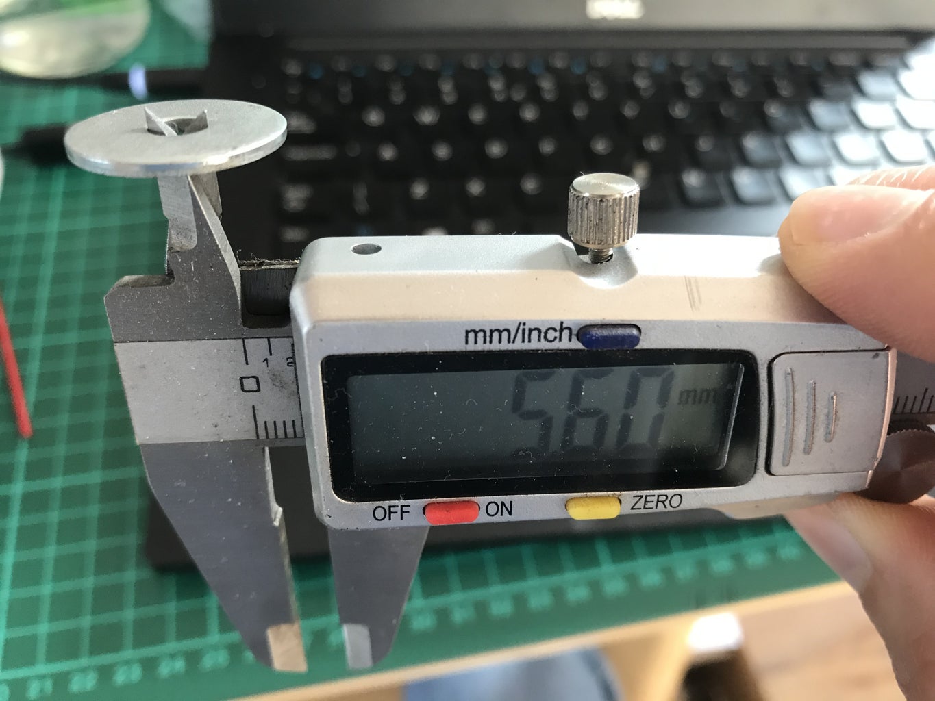
- 1x metal washer ID 5.5mm OD around 20mm (between 19.5-22mm is fine)
- A differential pressure sensor (approx. £10). We used a MPX5010DP but you may want to select a different one to suit the pressures in your system. Some example stores that sell these sensors are listed below:
- Pressure tap tubing cut to around 20mm length: Any 2mm OD rigid tubing should be suitable such as a brass tube. Out of desperation I used the spray nozzle from a WD-40 can, it worked but the super glue didn't stick brilliantly
- Super glue
- Silicon/PVC tubing for connecting to the pressure ports of the pressure sensor. 2-3mm ID should be fine, you may need a small cable tie if your tube is oversized. https://www.amazon.co.uk/sourcingmap-Silicone-Fle...
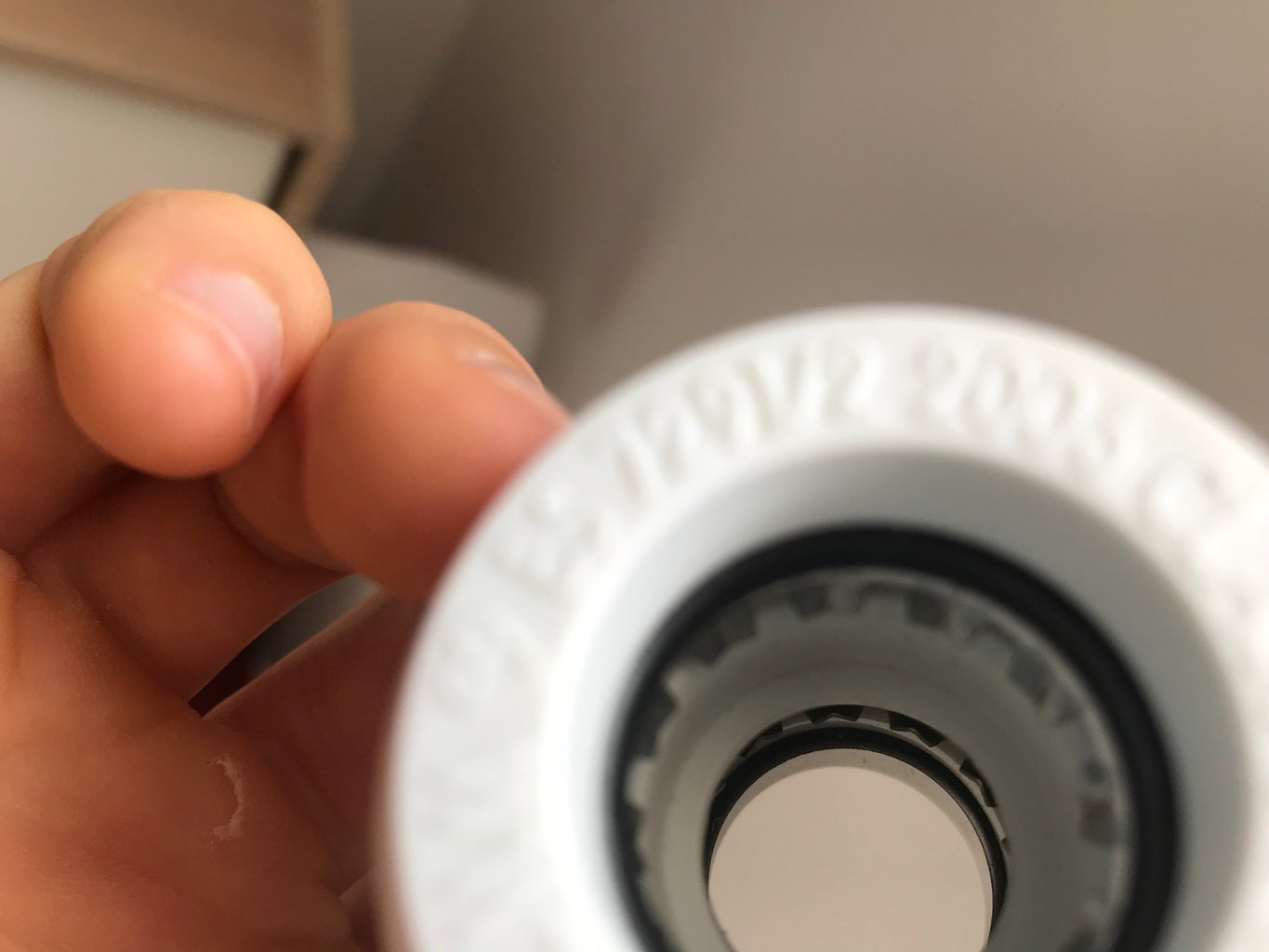
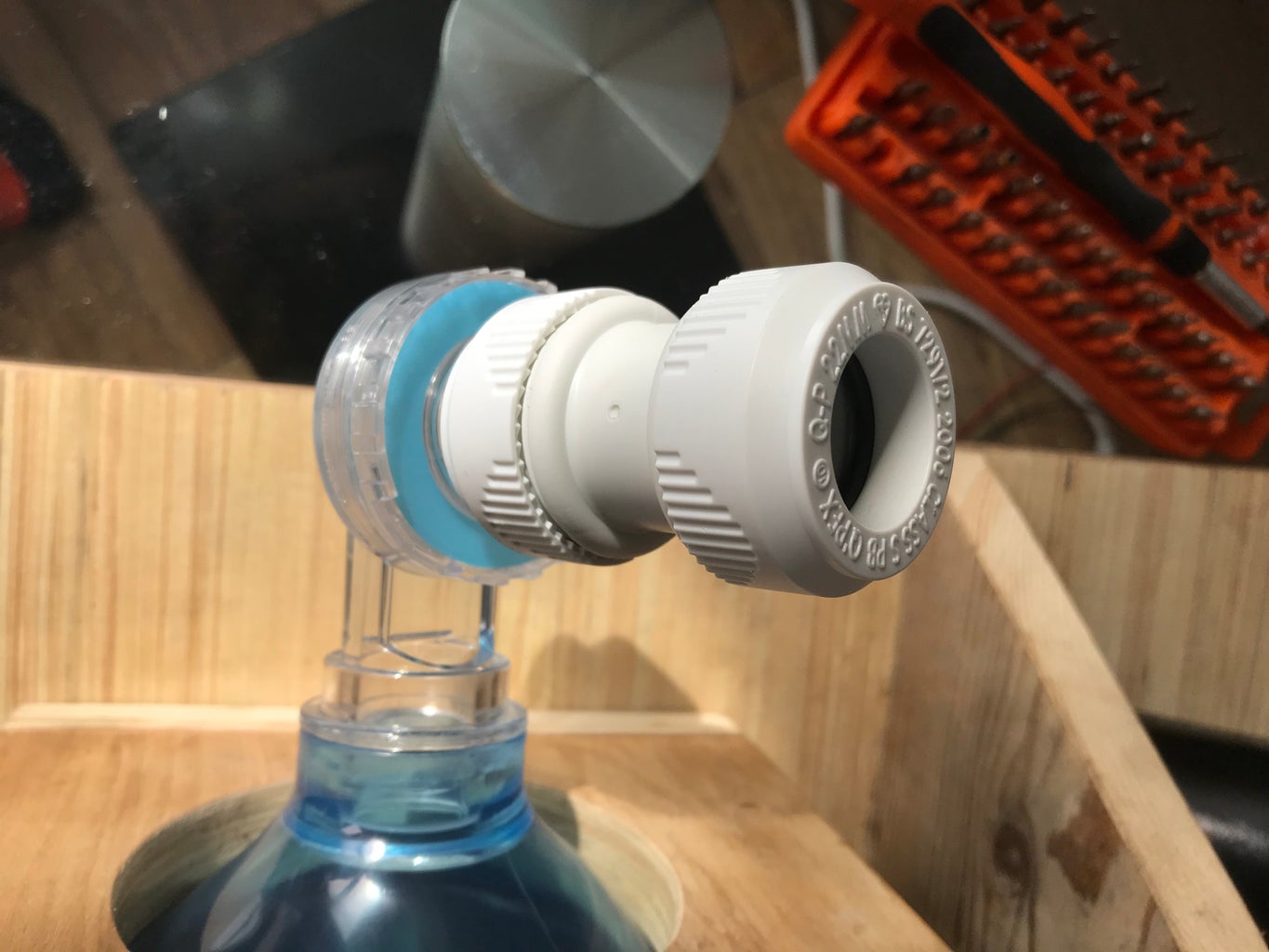
You may wish to buy 1 or 2 plumbing connectors if you want to fit the flow sensor piping onto another 22mm pipe : https://www.screwfix.com/p/hep2o-plastic-push-fit-...
Note: The materials chosen do not meet medical product regulations, particularly the PVC.
Step 2: Cut Plumbing Tube


Cut 2 lengths from the plumbing tube. We used 15cm length but it may work just fine a bit shorter. I made the cuts using a mitre saw as it's important to get a nice square cut. Use sand paper to smooth any burs
Step 3: Assemble Plumbing Tubes
- Superglue your washer to the end of one tube, make sure the washer is concentric with the tube and be sure to make a continuous bead of glue all the way around the circumference of the washer to ensure no air pressure will leak out.
- Then superglue the other length of tube to the other side of the washer. Again, make sure to glue all the way around so no air will leak out
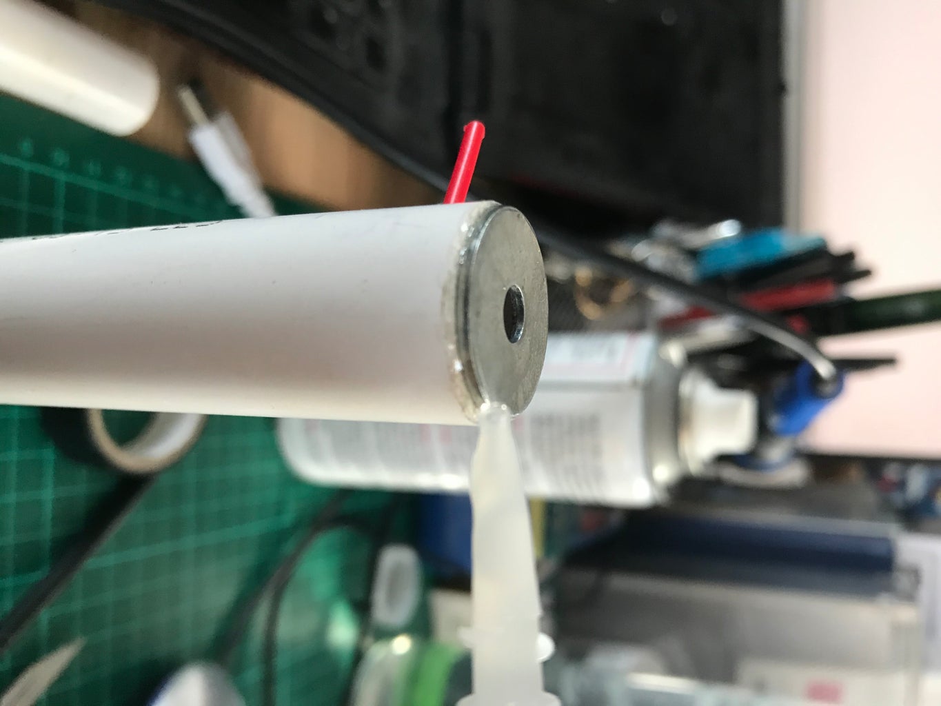
Step 4: Add Pressure Taps
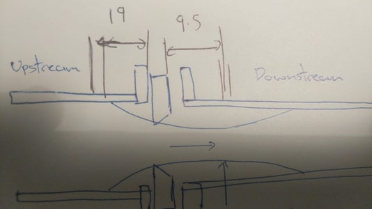


- Drill 2 holes at the distances from the washer according to the attached image
- Push the 2mm OD rods into the holes, make sure it's a tight fit (my tube was 2.2 OD but my drill bit was 2mm, so I just waggled the drill a little until the tube fit tightly)
- Superglue the tube into the hole, making sure it is sealed all the way around
- Wrap insulation tape around your pressure tap until the silicon tube fits on nice and tight
Step 5: Test and Calibrate


Connect the pressure sensor up to your Arduino and connect the pressure taps to the ports of the pressure sensor. Make sure that the sensor's physical analogue pin matches up with the pin the software.
Test it using the attached code. Note, the following libraries are needed:
- Wire.h
- and Sensirion_SFM3000_arduino (this library is for a different sensor, but I have made some changes in my code to account for that)
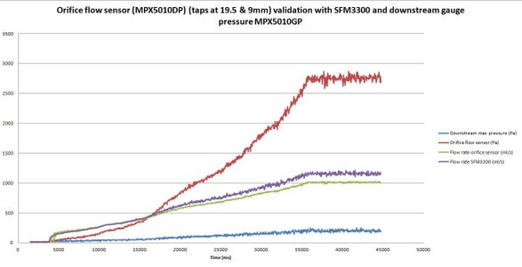
Ideally you want to calibrate your sensor, we used a Sensirion SFM3300 connected in series with the home made sensor. Connections for the SFM3300 are:
- Vcc - 5V
- GND - GND
- SDA - A4
- SCL - A5
Ideally your air source for the calibration test should give out a constant flow and be controllable to give out a controlled sweep of flow rates. We used an air bed pump hacked to be powered via an electronic brushed DC speed controller controlled using a potentiometer. If you have a DC power supply that will work just fine as well.
The code as well as being capable of reading the pressure and flow from our sensor, it can also read from the Sensirion SFM3300 via i2c, which is the sensor we used for calibration.You will need to adapt the code accordingly if you have a different calibration sensor. (Fairly amazingly the DIY sensor gave steadier more consistent readings than the SFM3300)
The 1st version of the code uses a calibrated lookup table to output flow rate readings. We made this by
- logging the pressure over a full sweep from our air source (as .csv file)
- taking the data into excel
- passing it through an equation to work out the flow rate
- then creating a comma separated lookup table that was copy/pasted into an Arduino integer array
The excel doc with equation is stored...
The second version of the code will use an equation in the code for the following reasons:
- to take into account temperature (which will affect the flow rate readings)
- to take into account a change in downstream restriction, this will be sensed with a separate downstream pressure sensor

Step 6: Proper Janky Calibration Method Option


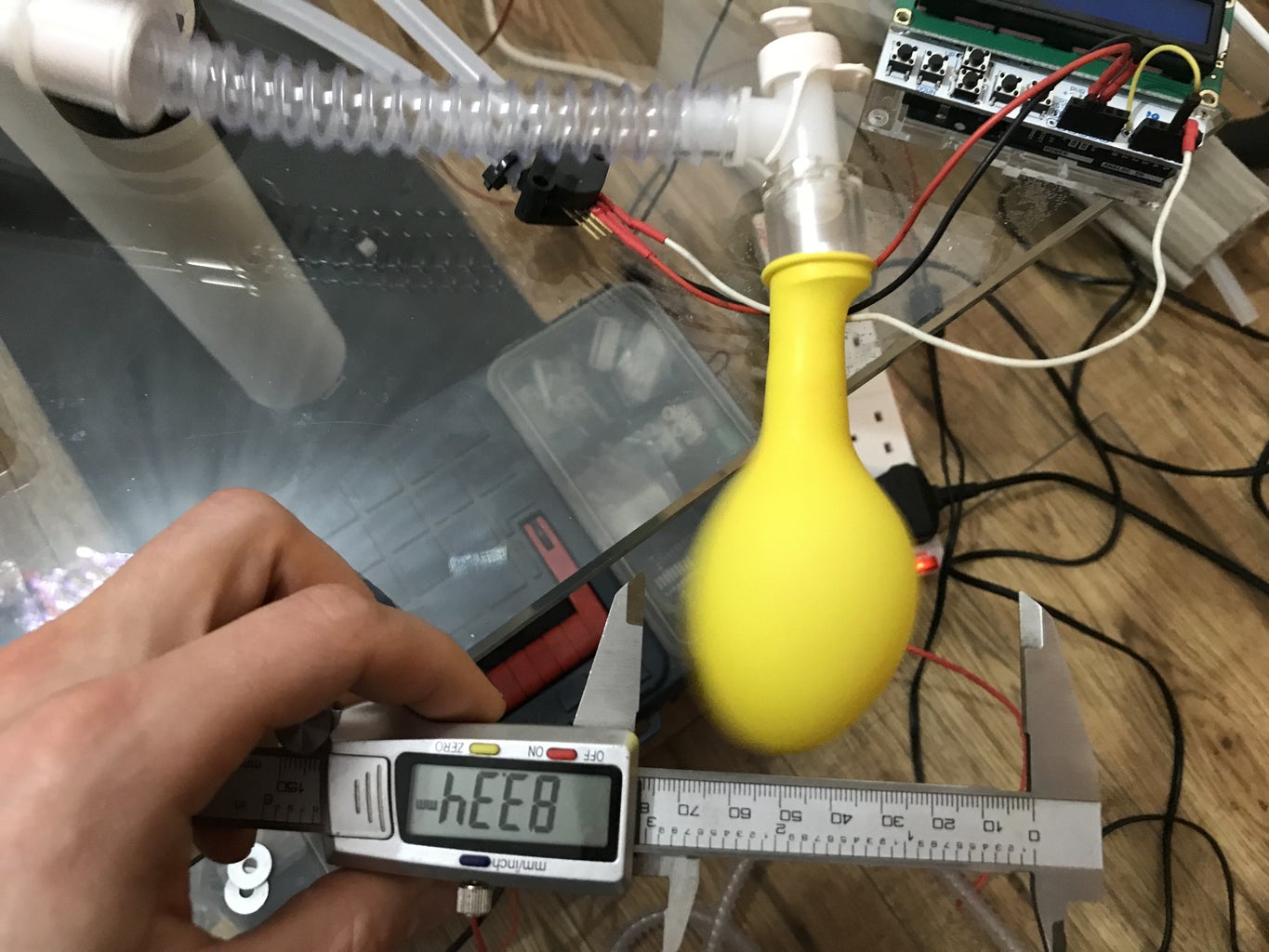

If you don't have an off-the-shelf flow sensor to calibrate it with such as a Sensirion SFM3300 then this is one way to get a SUPER rough idea of the flow output. However this will only work with a high pressure flow source (even the air bed pump might struggle to inflate a balloon) and will only work if you can repeatably turn on an off your air supply
- Attach a balloon to the output of the system and measure the diameter it inflates to on each inflation
- Fill a measuring jug with water (maybe about half way)
- Reinflate your balloon to that same diameter then completely submerge it in your jug of water and record the difference in the water level before and after the balloon is inserted
- Next you will need to measure the volume per balloon inflation in your code, this is done by integrating the flow over time. I can't give you exact code for doing this because it will have to be different depending on your flow source and how your code will sense a start and stop of the flow but I have attached a function in a text file that will out put volume, you will just need to tell it when to start and stop calculating the volume (i.e. for our test this was at the start and stop of each breath), this is indicated to the function via the boolean variable called "breathStatus". Remember to pass the flow rate in ml/s to that function when you call it.
Attachments
Step 7: Integrate Into Your System
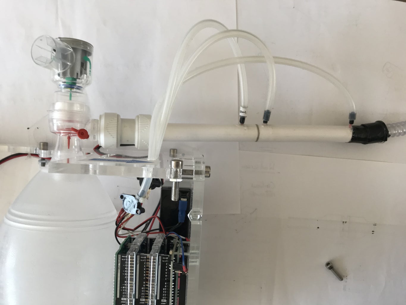

Plug it into your setup whatever it may be and enjoy measuring flow rate for under £15 :)
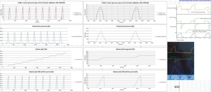
Attached is an example image of some flows, pressures and volumes from our ventilator application.
Plumbing straight coupling joints are great for joining this sensor to another 22mm OD tube.

Participated in the
Arduino Contest 2020


![Tim's Mechanical Spider Leg [LU9685-20CU]](https://content.instructables.com/FFB/5R4I/LVKZ6G6R/FFB5R4ILVKZ6G6R.png?auto=webp&crop=1.2%3A1&frame=1&width=306)


