

Introduction: How to Upload Sketches to an Arduino With a Broken Usb Port / Chip


Welcome to my very first instructable :)
Some time ago, I had a sensor connected to my Arduino Nano but the sensor didn't work, so I decided to get my multimeter to check the connections. I put one end on the 5V pin on the sensor and the other one on the ground pin, but some threw something on the table on with I was working and I accidentally short circuited the Arduino 5V and ground. then I heard the famous sound of a disconnecting USB device and all leds went dark.
After some research on the internet, I found out it's a diode which is probably broken and because of this it is no longer possible to power or upload sketches using the USB port. I found out it is possibly to send the Nano to a company for repair, it's free but you have to pay for the shipping and it's only for original Arduino boards.
Other solutions I found are replacing the diode, but it's a very small SMD diode and not everyone can solder SMD components.
The last solution I found on the internet is to upload sketches using an other Arduino as ISP. For this you need an other Arduino board and it's not that easy to do.
I had an USB to serial converter laying around to upload sketches to my Pro Mini and I thought: "If it's possible to upload sketches to the Pro Mini with this thing, it is probably also possible to use it to upload a sketch to other Arduino boards(the Pro Mini doesn't have an USB to Serial chip on board)."
I connected the serial converter to the Nanos RX/TX and power, and successfully uploaded a new sketch.
because I couldn't find anything on the internet about using an USB to Serial converter(USB to TTL) to upload sketches to all Arduino boards, I decided to write my own instructable.
So if you have an Arduino with a broken USB port or can't use the normal USB port for other reason, read this instructable and I'll show you how to save your Arduino.
Step 1: What Do You Need?


- An Arduino (any type except the ones that connects as hardware device(Leonardo / Micro) )
- USB to Serial converter(USB to TTL) general eBay link: http://www.ebay.com/sch/i.html?_odkw=usb+to+seria...
- Female-Female jumper wires(4 or more)
For boards with female pin headers you'll need:
- DuPont Female-Male jumper wires(4 or more) or some jumper wires(at least 4).
I used the PL2303HX as converter because I had that one laying around. To make this one work with Windows 8/8.1/10 you'll need to follow some additional steps. If you have a working device you can skip these steps(last step).
If you don't have a USB to TTL converter yet I recommend buying the FT232RL 3.3V-5V TTL USB SERIAL PORT ADAPTER, because this one has auto reset and has support for all Windows versions General eBay link: http://www.ebay.com/sch/i.html?_odkw=usb+to+seria...
I tested this methode with multiple Arduino boards, So far I successfully uploaded sketches to:
- Arduino Uno R3
- Arduino Pro mini
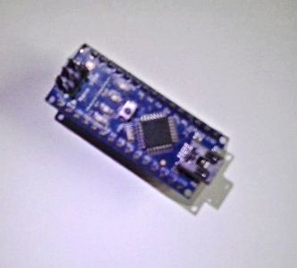
- Arduino Nano
- Arduino Mega R3(be sure to use Serial0 and not Serial1,2 or 3)
- Chinese clones of these boards
I also found out it's really hard(or impossible) to upload sketches to the Leonardo because it uses a different way to upload sketches. This probably counts for all boards that are able to communicate with the PC as a hardware device(i.e. a mouse or keyboard). So far I didn't succeed in uploading a sketch to this kind of boards but maybe I should try it some more time.
Step 2: Making the Connections


Making the connections is not hard at all, just follow these steps. To make it more clear, I included pictures and a diagram so you can see what I mean.
First plug the 4 DuPont wires to the 5V, GND, RX and TX of the USB to TTL converter, use the 3V3 line for 3.3V boards. Make sure you don't use the 5V for 3V3 boards because it will probably fry your board. Using 3V3 for 5V boards is no problem but it might not work as it should. When you connect both 5V and 3V3 to a 5V board the highest source voltage is used(5V).
Next, plug the other side of the wires to 5V and Ground, than connect RX to TX and TX to RX and plug the converter into your pc's USB port. Your connections should be like this:
PC USB port <---> USB to TTL
3V3 --- 3V3 on Arduino(only when using 3V3 boards)
TXD --> RX on Arduino
RXD <--- TX on Arduino
GND --- GND on Arduino
5V --- 5V on Arduino
Make sure to connect RX(receive) to TX(transmit) this is because on the one side the data is transmitted and received on the other side, so when you connect TX to TX both sides will send the data but none of them will read it because no data is send from RX.
Attachments

Step 3: Uploading a Sketch


Now that you have all the connections made and your device plugged into your pc, open the Arduino IDE, select the board you're going to upload your sketch to. You don't have to do anything with the USB to Serial converter, all it does is just converting the USB logic levels to TTL levels to be compatible with Arduino. beter versions have a reset connection to auto reset the board so it enters programming mode.
Make sure the power led on your board is on and the Arduino is recognized by the IDE and Select the right COM port.(if your device is not recognized go to the last step)
Now check your sketch and press the upload button. If you have a converter with auto reset function than the converter will pull the reset line on the board low before starting to upload. The reset line on the Arduino needs to be pulled low so the bootloader is activated and you can upload new sketches to the board.
If you have a converter without a reset line you have to manually put the board into programming mode before uploading a new sketch. To upload a sketch simply press the upload button, press and hold the reset button on your board and wait for the program to start uploading, ones it starts uploading, release the reset button and your sketch should upload. Try uploading the FastBlink sketch and wait for it to upload, if it's all successful the led should start blinking twice and than wait a little while.
To make it easier for you to see when you should release the reset button I recommend to enable advanced output during compiling and uploading, to enable this:
- go to file>preferences
- select the boxes for advances output during compiling and uploading
- you might need to restart the IDE
You should press the reset button when a lot of (white) text is thrown to the debug screen(see image) and when the text turns orange and says something like "overriding baudrate" you should release the button, if it's al OK you'll see something like this: 'UPLOADING...............' followed by 'READING / VERIFYING...................... done. sketch uses 1.234 bytes (27%)' or something like that.
If you see something like 'failed to upload' or 'programmer not responding' that means you pressed the button to late or didn't release it in time, just keep practicing till you succeed.
If you get the message 'Board at COM3 not available' you probably connected RX to RX and TX to TX or selected the wrong COM port, if not continue to the next step.
Attachments
Step 4: Install USB to TTL Drivers for Windows 8/8.1/10


Since the update to Windows 8 and later Windows 10, my USB to Serial converter is no longer supported by the drivers because Chinese clones use the same driver. To stop this the manufacturer 'kicked' al chips except the latest ones. I will now show you how to fix this problem.
- go to device manager(search: 'device manager')
- click on ports(COM & LTP), there will be a warning sign at com3(or other com port)
- right click on the prolific USB to Serial COM port and click properties
- go to the driver tab in the menu on the top
- click edit driver
- click the search for local drivers button
- select the one from 2008 and click next
- wait for the driver to install and click finish / close
- the driver should now be installed
In case you don't have the right driver on your pc you can download it here http://www.prolific.com.tw/UserFiles/files/PL2303_...
Make sure you run it as admin, you might need to reboot your pc.
I hope I prevented you from throwing your 'broken' Arduino away and that this instructable was helpful for you.
If you have any questions you can always send me an email.
If you liked this instructable please vote for me, thank you very much.

Participated in the
Arduino All The Things! Contest

![Tim's Mechanical Spider Leg [LU9685-20CU]](https://content.instructables.com/FFB/5R4I/LVKZ6G6R/FFB5R4ILVKZ6G6R.png?auto=webp&crop=1.2%3A1&frame=1&width=306)


