

Introduction: Image Processing Without a Computer


This instructable will show you a simple way to do some pretty advanced image processing using nothing but optics - not a computer in sight! You won't require any professional optics hardware, the components are pretty low cost and perfect alignment is not required... a perfect dining room table optics project!
We will use an arrangement called a 4f correlator to transform an image into its Fourier transform, filter it in the Fourier domain, and then reverse the transformation to reconstruct the (now processed) image. I will explain all the aspects of what these are and how this demonstration works in the following steps.
For now, suffice it to say that Fourier domain filtering enables most image processing done on computers; it can create many filters from simple blurs (including directional blurs) to edge detection and enhancement, right through to image identification (or correlation).
While it might not be as easy as applying the same filters in Photoshop, this is an impressive demonstration that will show both the basics of Fourier image processing and the strange effects you can get from diffraction caused by the wave nature of light. And it does outscore computer processing in one way, the processing is performed literally at the speed of light!
To make this you will need the following low cost, off the shelf components:
- Telescope (mine isn't that cheap but a £16 beginner's scope would work)
- Very bright LED (I used a Cree 3W LED)
- 2x convex lens. I used the lenses from two Smart phone projectors (you get one lens with each projector)
- Stands - I used retort stands although you could make stands from scrap wood, etc.
- 35mm projector slides (possibly half frame slides if like me you use a camera without a full frame sensor)
- Bulldog clip to hold the slide
- Tin foil, pins and cocktail sticks for filters
- Something to 'read' the filtered image:
- Ideally, a camera with removable lens and relatively large sensor (such as an SLR),
- Although a sheet of paper to project onto would also work.
The first 3 steps detail how the arrangement works, if you just want to build it skip to Step 4...
If you like this instructable please vote for me in the Optics contest :)
Step 1: Introducing the Fourier Domain

(While recommended for understanding the arrangement, this step isn't strictly necessary to build the set up)
As I said before, most image processing is applied in the Fourier domain, but what is the Fourier domain?
There is an interesting way of thinking about any arbitrary function or signal, that goes like this:
You can build any signal by summing a series of sine waves of ever increasing frequencies, called a Fourier series. To work out the amount of each sine wave to add to make a particular signal we use a mathematical transformation called the Fourier transform.
This can be done in 2 dimensions by adding a 2 dimensional series of sinusoidal stripes (the two dimensions being the spatial frequency and angle), and this is how jpegs store images. If each of these sinusoidal stripes is represented by a position in a plot where vertical position is the vertical stripe frequency and horizontal position is horizontal stripe frequency, this is the the Fourier transform of the image. The Fourier transform is the same image, just represented differently, so we say it is the image in the Fourier domain.
The image above is a computer generated Fourier transform of the lighthouse picture used as an example throughout this instructable.
If you want a more visual explanation see these youtube videos (neither are mine):
This video inspired my build, and it goes on to describe much of the setup.
Step 2: Introducing Diffraction and Fourier Optics


(Also not required for the build, but fundamental to understanding how it works)
Light is a bit funny in that sometimes it behaves like a particle, and sometimes it behaves like a wave.
Diffraction of light is an effect that is due to the wave-like nature, and it causes light to bend in ways not anticipated by classical ray tracing optics of Newton's era.
Diffraction is the way waves radiate out from edges and corners.
If a surface wave travels on water, each bit of wave is kept together because its high pressure is matched either side by the pressure of the next door bits of wave. When the wave meets an obstruction such as a wall, there is momentarily a period of pressure as the wave hits, which normally causes the wave to reflect backwards. If there is a gap in the wall, the bit of wave in line with it passes through the gap with pressure either side supported by the edge of the wall, but as the wave leaves the gap its edges are unsupported and the wave spreads out in a circular pattern. If the wave encounters a single edge (like a harbour wall) the end of the wave spreads to fill the space behind the wall in the same way. Because the charged particles that make up matter restrict the electromagnetic field from moving freely as light passes, light travelling past an obstruction also spreads (or diffracts) into the space behind. This isn't a phenomenon we are used to seeing, but it does cause some strange effects (like why floaters in your eyes look like rings). This bending of light also creates a limit of resolution of telescopes and other optical systems, due to diffraction created by the aperture of the lens or mirror used.
The second image is a photo I took of the shadow cast in a laser by a ball chain of the type often used to attach plugs to sinks. Classical ray tracing would suggest a hard edged shadow in the shape of the chain, but we actually see light inside the shadow with ripple effects around the edges caused by light diffracting into the shadow behind the chain.
When light passes through an image such as a projector slide, the variations in the filtered light caused by the detail in the image have a similar effect; they cause diffracted waves of light to spread out from the detail that caused them. Because the sharper the disparity in the filtered light (that is to say the sharper the gradient of brightness in the image), the more strongly it is spread, this creates a pattern that depends on the spatial frequencies within the image. If the classical image rays are focussed to a spot by a lens that is one focal length away from the slide/image, this pattern is actually the Fourier transform of the image!
Step 3: The 4f Correlator

(Last slide on the understanding, the next will move onto the build)
The 4f correlator is an arrangement that transforms an image into the Fourier domain and then transforms it back to an image. Theoretically no change is made if no filter is added, but by passing the light through a plane where it is the Fourier transform of the image, we can apply filters to the Fourier domain, and the reconstructed image is the resulting image from the processing associated with the applied filter.
In order to do this, the arrangement mirrors the Fourier transform lens arrangement from the previous step.
Collimated light is passed through an image (such as a projector slide) one focal length in front of a first lens, which then creates a Fourier plane one focal length behind this lens, where only the now diffracted light deviates from the focussed spot of classical image rays. One focal length behind the Fourier plane, a second lens is added. By this distance the classical image rays have passed back out of their focussed spot and have spread back to the full size of the slide, but inverted. This lens effectively recombines the diffraction waves with the inverted image rays which are now re-collimated. One focal length behind the second lens, the diffraction waves are refocussed to create the detail that created them.
If we place an obstruction in the Fourier plane (half way between the lenses) to block out some of the light, we are removing certain frequencies. For example if we stick a ball in the centre we obstruct the DC and low frequency components of the image, and we are left with the edges glowing brightly. Conversely, if we place some foil with a small circular hole in the centre, we obstruct all the high frequencies, resulting in a blurred image. We can also select frequencies of a certain direction, for example a slit allows all frequencies in one direction but is a low pass filter in the other direction, so a central horizontal slit gives a vertical blur to the image.
We could add more complicated filters... in fact, if we put a slide with the Fourier transform of a small part of an image we are looking for, the output would dim most of the image, but highlight this sub image brightly regardless of where in the image it is placed. This was used to search for known shape targets (e.g. tanks) in spy plane photography. The film could be passed through quickly (played like a movie) and if a frame had a matching shape, the output would brighten. This matching process is known as correlation, and, with the arrangement over four focal lengths, this gives the 4f correlator its name.
Step 4: Collimating the Input Light


(Starting the build)
We need collimated light to shine through the slide. Collimated means all of the rays are parallel, with none crossing over at all. To do this we need to focus something (lens or mirror) on a point source of light. The easiest option for me was to use a telescope, which I will describe below, but a lens (even a camera lens focussed at infinity) could be used.
I made a small circular hole in some tin foil using a cocktail stick, and wrapped this over where the eyepiece normally goes. I then shone a very bright LED into the hole. I had a 3W LED and LED driver to hand so I used these, although a bright front bike light or the like would also work.
This projects a beam out of the telescope aperture, the size of which can be adjusted by moving the focuser. The easiest way to ensure good collimation is to measure the width of the beam at two distances as far apart as possible, and adjust it until the beam width is the same at both distances. My telescope has a 127mm mirror, and you can see that the beam is 127mm shone on a door close by and when shone across the width of my house.
If you use a lens, you can still measure the beam to ensure collimation, but the fine control of the focuser makes the telescope much easier.
Once finished, use more tin foil to catch as much stray light as you can.
Step 5: Aligning a Slide and Lens One Focal Length Apart


I used a retort stand to clamp both a lens and a bulldog clip (which would hold the slide). Having made a collimated light source, focussing this pair is easy. Clamps some stiff paper (I used an envelope) in the bulldog clip and place the lens in the beam. Ensure the lens is perpendicular to the paper, and see how the beam is focussed. Adjust the separation until the spot is as small as it will go (flexing the paper forward and back will help you tell).
Once you are happy, turn the entire retort stand around and fit the slide to the bulldog clip and align so the light shines through the slide and then into the lens. Place the paper after the lens to ensure the whole image is passing through unobstructed.
Also, if using a Newtonian telescope, ensure you are using part of the beam that is free from shadows of the primary or spider.
Step 6: Aligning a Second Lens Two Focal Lengths From the First Lens


Attach some tissue paper over the surface of the second lens (e.g. using a rubber band). Place the second lens in the projected image beam and axially align it as well as possible. Move it until the image projected on the tissue fits within the lens and is the same size as the slide (my slide was exactly 35mm, but watch out, they can be 34-36mm!).
Remove the tissue.
Step 7: Positioning the Camera One Focal Length From the Second Lens


Attach the camera to a tripod and remove the lens. Adjust the position until the image beam falls on the sensor. Use the camera to view the image, and adjust the distance from the second lens until the sharp lines and edges are as sharp as possible.
If you don't have a suitable camera then arrange a piece of stiff paper or card behind the lens, and adjust separation to maximise sharpness.
Your 4f correlator setup is now complete!
IMPORTANT: If you do use a camera, remember to fit a lens whenever you are not using it and try to avoid getting dust on the sensor.
Step 8: Fourier Filtering to Apply Processing to Images


Note: these photos have not been digitally adjusted in any way, they are the raw output from the camera using the different filters I tried.
Fourier filtering has to be done exactly half way between the two lenses, where the beam is most densely focussed down. Try sticking a pin (preferably with a round head) right in the centre. This should filter the DC and low frequency signals, leaving the image dull with the edges very bright (Picture 4 filtered vs. picture 3 original)
Placing a vertical or horizontal slit in the beam gives the horizontal or vertical blur found in pictures 5 and 6 respectively. A piece of foil with a hole in placed above or left of centre gives the horizontal and vertical edge detection from pictures 7 and 8 respectively, where placing the hole in the centre gives the blur of picture 9. Picture 10 (annoyingly mirrored because I put the slide in backwards) was also created using the pin head in the centre but it seemed to let more DC light through, giving a really brightly coloured image.
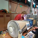
Picture 11 shows the camera capturing this image.
At this point I'd say have an experiment. Try putting different things in the Fourier plane and see what happens. Post photos in the comments if you get any good results!
I hope you have found this instructable interesting. If so please vote for me in the optics contest :)

Second Prize in the
Optics Contest


