

Introduction: Instrumenting a 3D Printer (or Whatever)


This project started with me wanting to instrument a beta unit 3D Printer that I had recently acquired. The printer, a Wanhao D7, is an incredibly low priced resin based printer capable of 35 micron resolution in the z-axis and 50 microns on the x-y axis.
Anyway, the question that I wanted to answer was in regards to cooling and what was needed from a fans perspective. I did a quick and dirty solution that allowed me to use an Arduino Nano connected to a light sensitive resistor (photo resistor) and three heat sensitive resistors (thermistors).
The graphs shown above were created from the data captured from my little monitoring solution.
Step 1: Parts Needed

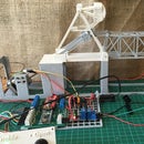
Below are the parts needed for this project. They tie to the photo!
- PCB - Should be available for purchase on eBay here.
- Arduino Nano
- Power Regulator - Takes 12v in and delivers 5v for the PCB - There are at least two on eBay that will fit this need (search for "DC/DC Step Down Adjustable 24V 12V to 5V Power Converter")
- Headers for the Nano - You can surface mount but I recommend using headers
- Leads for Power - Connected to 12V power supply
- Photo Resistor - Used as part of a voltage divider to return a light reading. Search for "Photo Light Sensitive Resistor Photoresistor"
- Thermistors - Used as part of a voltage divider to return a temperature reading. Search for "Thermistor Temperature Sensor"
- Bluetooth Module - Communicates a stream of readings back to a host computer. Search for "Wireless Bluetooth HC-06 RS232 Serial Transceiver Module Arduino"
- Resistors (6x10k) - Two resistors are used for the LEDs and the others are for the sensors voltage dividers.
- LEDs (Red and Green) - Self explanatory
- Buzzer - Current code does not use this but it could! Search for "Active Buzzer for Arduino"
- Connector for Relay - Self explanatory. Could do without and just solder connectors.
- Relay - Search for "5V 1-Channel Relay Board Module for Arduino"
Step 2: Prepare the Sensors

Solder leads to each of the sensors (photo resistor and three thermistors). Use shrink wrap tubing to insulate exposed conductors.
Step 3: Mount Components on the PCB


At this point we solder most of the parts we have gathered to the PCB. This includes the header for the Arduino, and in this case, ones for the Bluetooth Module, the Power Regulator, and the optional SPI interface pins. It also includes:
- Power Regulator
- Resistors (6x10k)
- Buzzer
- Connector for Relay
Note that in the picture I have inserted the Arduino Nano and the Power Regulator into the headers on the PCB.
Step 4: Connect Sensors, LEDs, and Power Input Leads

At this point leads should be prepared for the two LEDs as we did for the sensors. All of these leads should then be soldered to the PCB. Remember polarity on the LEDs...also remember which is red and which is green! Note that the current version of the PCB does not have a breakout for the power input leads. Due to this oversight the power input will need to be connected directly to the pins that are provided. I chose to do this by using the pins from the headers as they protrude far enough below the PCB to be manageable for this purpose.
At this point you may also choose to print a mount for the PCB and relay. It is available here.
Step 5: Ready to Install

All components have been mounted on the PCB, the PCB has been attached to the mount, as has the relay.
Step 6: Install in Chasis

Here the mount with the PCB and relay has been placed into the chassis. I have used velcro for this purpose. Shame on me. Note that the other end of the power lead has now been attached to 12v power.
Step 7: Position the Sensors


As the title states!
Step 8: The Code
The code that drives this can be found here.


