

Introduction: Interfacing Motors With Arduino


Interfacing different types of motors with a micro-controller is among the most fundamental skills a maker/robotics enthusiast needs to master. In this project I'll build up on the previous project Smart Phone Controlled LED Lights using HC-05 and Arduino UNO. We'll go ahead and interface 3 different types of motors viz:
1. BO DC Motor with plastic gears using L293D Motor Driver
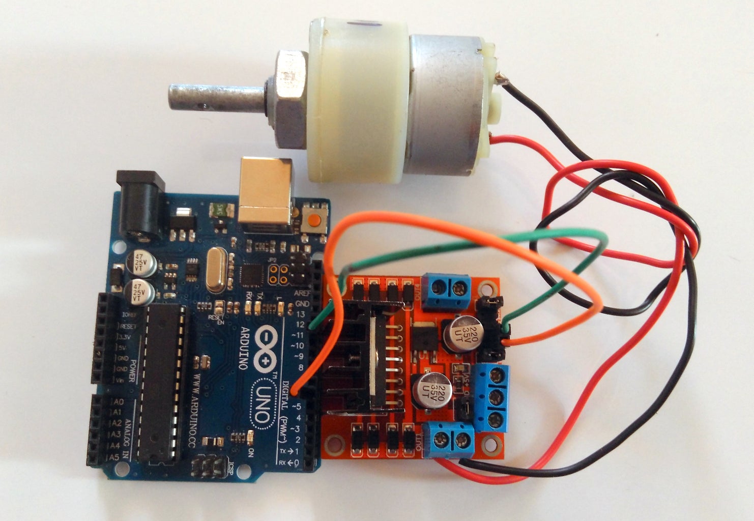
2. Metal Geared DC motor with ~3 Kg-cm torque and 100 RPM using L298 Motor Driver
3. Servo Motor with metal/plastic gear 10 Kg-cm torque.
We'll use the same Bluetooth Terminal app to send different commands and control these motors likewise.
Components:
- DC Motor with metal gear 100 RPM
- BO Motor with plastic gear 150RPM
- Servo Motor with metal Gear along with accesories
- L293D Motor Driver Module
- L298 Motor Driver Module
- Universal Battery eliminator (UBEC) 5/6V 5 A output
- Arduino Uno
- HC-05 Bluetooth Module
- Plastic Wheel 5 cm diameter 6mm shaft
- Plastic wheel 5 cm diameter BO motor compatible
- Motor bracket for DC metal geared motor
Step 1: Connect All the Hardware
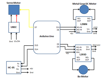
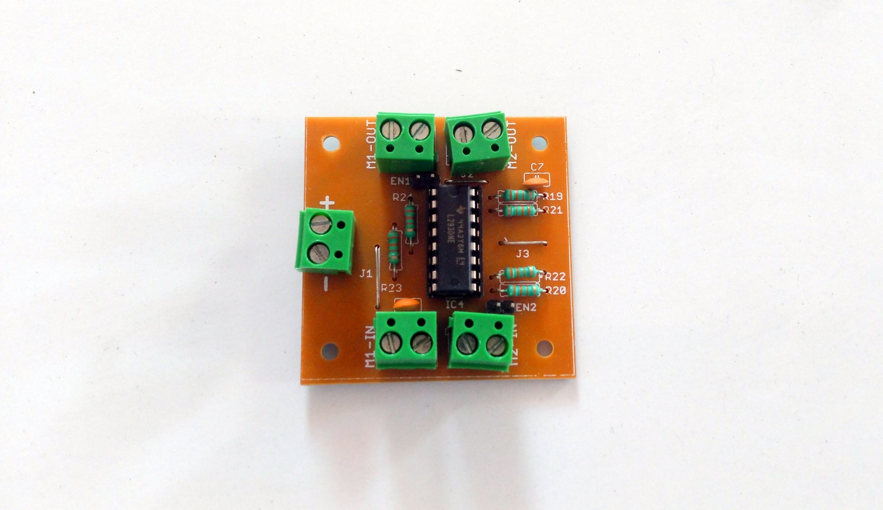


Connect the L293D Motor Driver
L293D is a dual full-bridge motor driver with a maximum output current of 600 mA per channel (data Sheet). Which implies you can simultaneously drive 2 motors which have a current demand within the limitations of the IC. In our case, we are using only a single channel, which implies We'll use the M1 IN/ M1 Out ports on the module (Pins 2,7 and 3,6 respectively on the IC). In order to enable the motor connected to this channel, we need to pull the EN1 (pin 1) HIGH. The module I am using has provided a simple jumper arrangement to hard wire this, see the picture for reference. Alternatively you can control this pin via your controller. the pin connections are as illustrated in the figure.
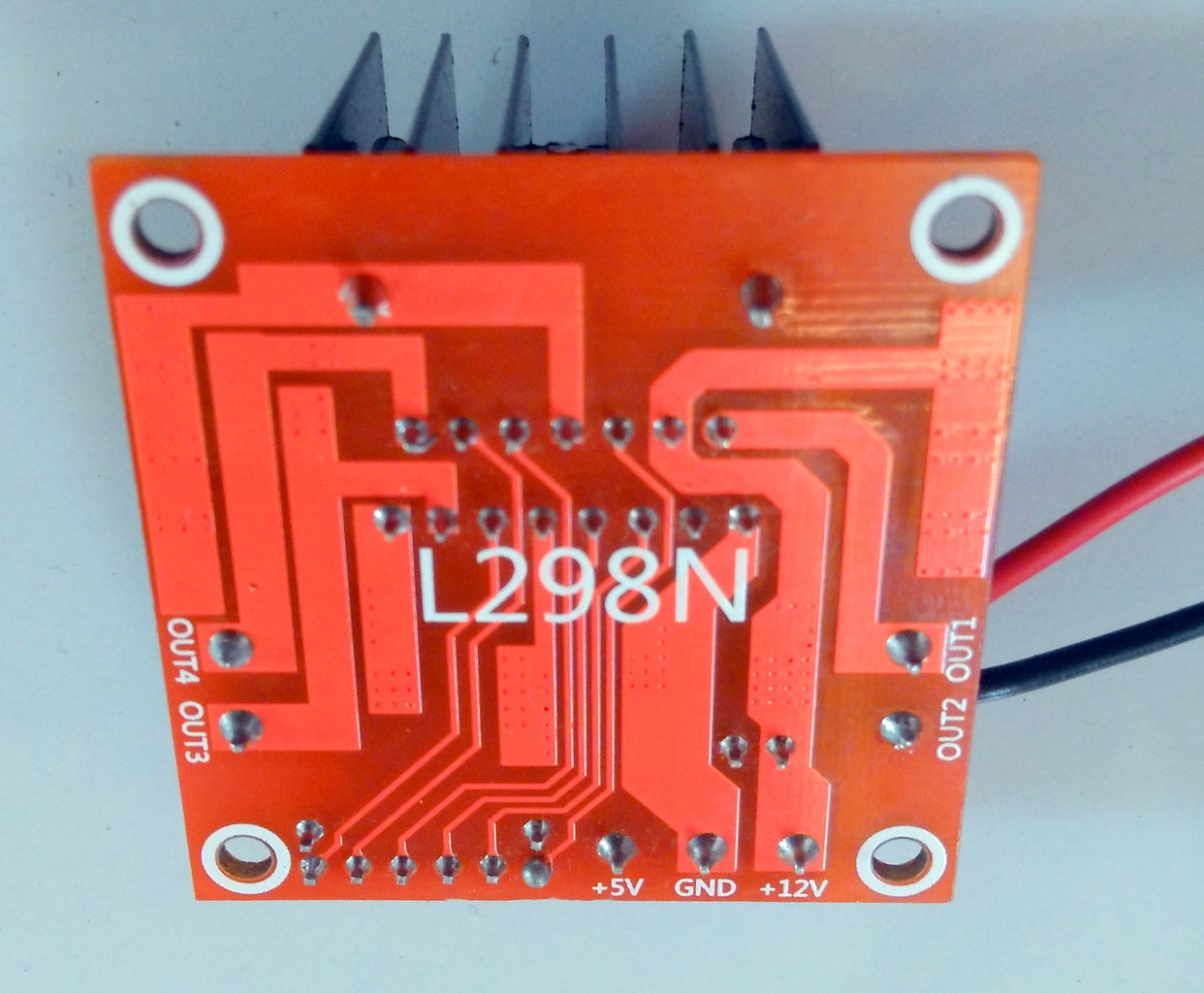
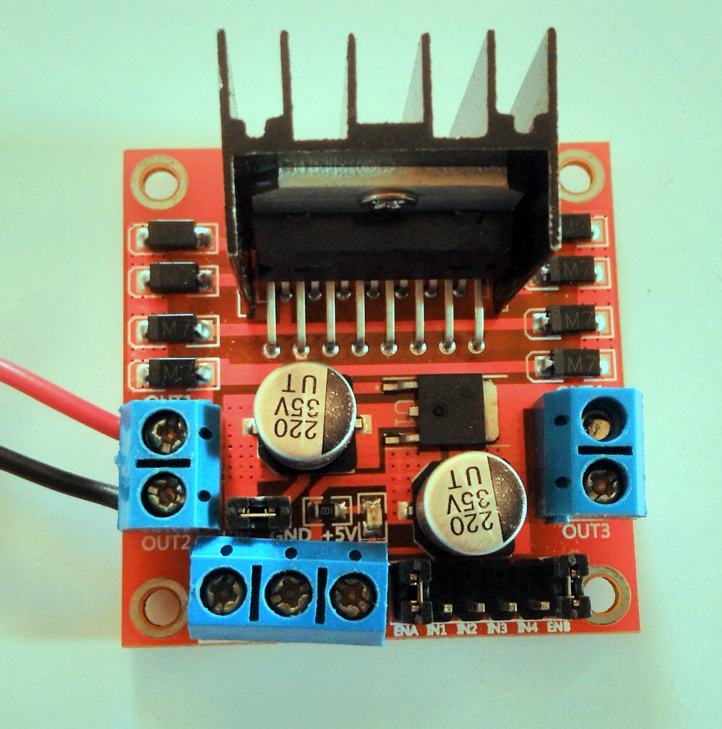
Connect the L298N Motor Driver
Similar to L293D, L298N is also a dual full-bridge motor driver with a maximum output current of 2A per channel. We'll be using only one channel ie. M1,M2 (This module has a different naming convention and M1-In,M2-In are inputs and M1-Out,M2-Out are the corresponding outputs ) Data Sheet L298N
When we need more current like in case of a metal geared DC motor, this particular driver is a pretty good choice. It allows for good performance, low heating (although using a heat sink is recommended and most modules available in the market come with a heat sink). It's also a very cheap, that helps.
Connect Servo Motor
Servo Motors come in a variety of sizes and corresponding torques ratings. Often we see motors with a lower torque rating use plastic gears, but those with higher torque rating, use metal gears.
A servo motor has 3 wires coming out from it, viz Signal, Vcc and Ground. Generally the colour code used is as follows:
Signal>Yellow/Orange; Vcc>Red/White; Gnd>Black/Brown
As a rule of thumb, the easiest way of identifying them is, The Darkest one is ground, the slightly brighter is Vcc, the brightest one is the Signal.
If you are using a micro servo like HK15178 , you can power it using the 5V pin on your Arduino. However, when the current requirement is higher, your Arduino cannot supply enough current and hence you need to power it externally. We'll use an Universal Battery Eliminator Circuit (UBEC), which has a convenient 5V/6V 3A Output. The reason we are using this circuit over a simple voltage regulator like 7805 is the current limit for the voltage regulator is lower than the desired output for controlling a servo which is around 1.5 to 2 A (depending on its rating).
PS: If you power a higher rating servo using your Arduino, the board might abruptly reset and behave in an undesirable way.
Connect HC-05 Bluetooth Module
This step is exactly similar to the one explained in Smart Phone Controlled LED Lights using HC-05 and Arduino UNO The only difference here is that We are using Analog Pins A0 and A1 as Digital Pins (D14 and D15) for Rx and Tx.
Step 2: Arduino Code
#define BoMotor_F 3
#define BoMotor_B 5
#define DcMotor_F 6
#define DcMotor_B 11
#define ServoMotorPin 7
#include
#include
SoftwareSerial mySerial(14, 15); // RX, TX
Servo myservo;
char character;
boolean flag=false;
void setup() {
  // put your setup code here, to run once:
mySerial.begin(9600);
Serial.begin(9600);
pinMode(BoMotor_F,OUTPUT);
pinMode(BoMotor_B,OUTPUT);
pinMode(DcMotor_F,OUTPUT);
pinMode(DcMotor_F,OUTPUT);
myservo.attach(ServoMotorPin);//servo is attached on pin7
}
void loop() {
  // put your main code here, to run repeatedly:
 String Data = "";
    flag=false;
    while(mySerial.available()) {
     character = mySerial.read();
     Data.concat(character);
     flag=true;
     delay(100);
    }
if(flag)
    {
     Data.trim();
     Serial.println(Data);
     int s = Data.substring(0,1).toInt();
     int direction = Data.substring(2,3).toInt();
     int value = Data.substring(4).toInt();
     switch(s){
      case 1:{DcMotor(value, direction); break;}
      case 2:{BoMotor(value,direction);break;}
      case 3:{ServoMotor(value,direction);break;}
      case 0:{DcMotor(0,direction);BoMotor(0,direction);break;}
               }
    }
}
void DcMotor(int speed, int dir)
{
  analogWrite(DcMotor_F,(speed+dir*speed)/2);
  analogWrite(DcMotor_B,(speed-dir*speed)/2);
}
void BoMotor(int speed, int dir)
{
  analogWrite(BoMotor_F,(speed+dir*speed)/2);
  analogWrite(BoMotor_B,(speed-dir*speed)/2);
}
void ServoMotor(int angle, int dir)
{
  myservo.write(angle);
  delay(2000);
  myservo.write(0);
}
Step 3: Connect With Your Smart Phone
Similar to the previous article on Smart Phone Controlled LED Lights using HC-05 and Arduino UNO we will go ahead and connect our smart phone to the arduino via HC-05 Bluetooth module.
The Command we are going to send is as follows:
Say I want Dc motor to run at a PWM value of 200 in forward direction, i'll send:
1,1,200
if the same dc motor were to be running at a PWM of 150 in reverse direction, I'll send:
1,-1,150
In general the format is: Motor,Direction,Value
Motor: 1>Dc Motor, 2>Bo Motor, 3> Servo Motor, 0> stop everything that is running (peace :P)
Direction: 1> clockwise/forward, -1>anticlockwise/reverse
value: PWM value from 0 to 255; in case of servo this is the angle
PS: In case of Dc motor and Bo motor, if you find that the motor is rotating is the opposite direction then what was intended, just interchange the pin numbers assigned in the program for forward and backward pins'
eg: original
#define DcMotor_F 6
#define DcMotor_B 11
Exchanged
#define DcMotor_F 11
#define DcMotor_B 6


