

Introduction: Introduction to 3D Machining


This class is for anyone who wants to learn:
-CAM (Computer Aided Manufacturing) in Fusion 360
-3D Toolpathing for components using a flip to machine both sides
-CNC machining in wood
3D toolpaths are machining operations in which the tool moves dynamically in three directions (X, Y, and Z), but stays perpendicular to the machine bed. 3D toolpaths are great for machining complex or organic shapes, because they can follow the changing surfaces of these shapes. 2D or 2.5D toolpaths, which can't move dynamically in Z, are used for prismatic shapes that contain a flat bottom and vertical sides.
In this class, you’ll learn how to machine a wooden serving spoon using CAM (Computer Aided Manufacturing) in Fusion 360. You'll work with multiple setups, choose workholding, build registration systems, create and constrain 3D toolpaths, and post process your file to G-code. Afterwards, you'll learn how to machine the spoon yourself using a DMS router. You'll learn how to prepare and install your stock, insert and measure tools, establish a WCS (Work Coordinate System), and load and run programs.
Step 1: Machining Strategy

Before beginning CAM programming, you need to consider the part and the best approach to machining. These decisions depend on the shape of the model, the material, and the constraints of the CNC machine you are using. In this lesson, you will learn how these factors impact your machining strategy with respect to workholding, registration (making sure the CNC knows where the part is), and CAM settings.
Step 2: 3D Toolpathing
If you completed the CAD and CAM Class, you worked with 2D toolpaths, in which the end mill stays at a fixed depth (Z-level) throughout a machining pass, moving only in X and Y while cutting. This type of machining is ideal for prismatic parts - parts in which all machined faces lie normal to the machine tool spindle.

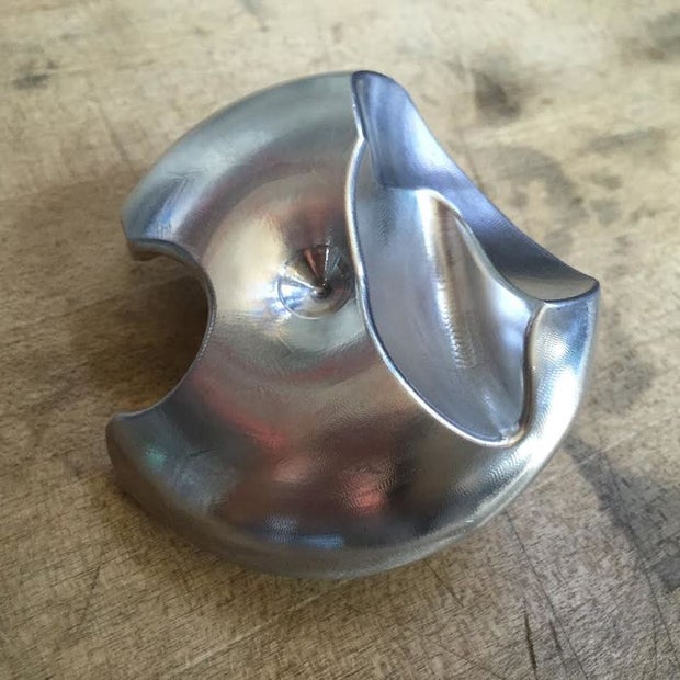
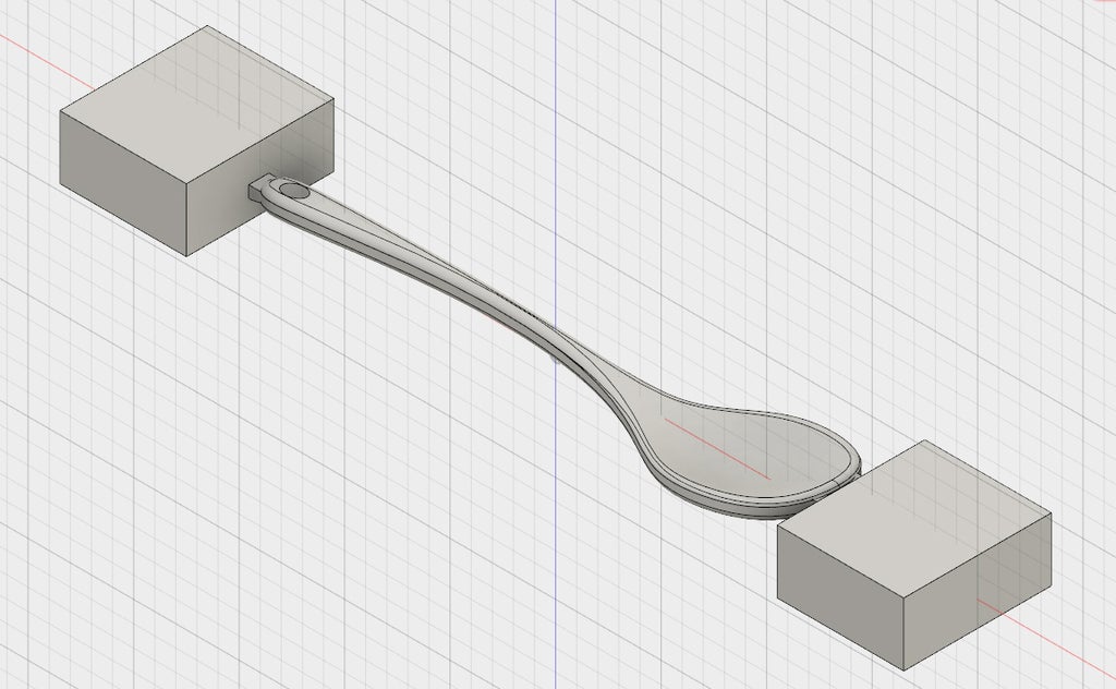
When programming non-prismatic parts, such as molds or organic shapes like the the parts below, 2D operations are insufficient. You need to use 3D CAM operations, in which the end mill moves dynamically in X, Y, and Z.

Step 3: Workholding

Workholding is the strategy for holding your part rigidly during the machining process. When programming with 3D toolpaths, workholding is an important initial consideration. This is especially true of parts that require machining on both sides, when the part will be flipped between setups.
When programming for prismatic parts, you may have noticed that 2D and 2.5D CAM only requires a CAD model of the part that you want to machine, without any extra features for workholding attachment or registration. This is because the part takes the shape of a rectangular prism, which can be held easily inside a vise or fixed to a spoiler board.
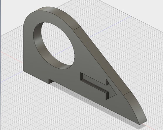
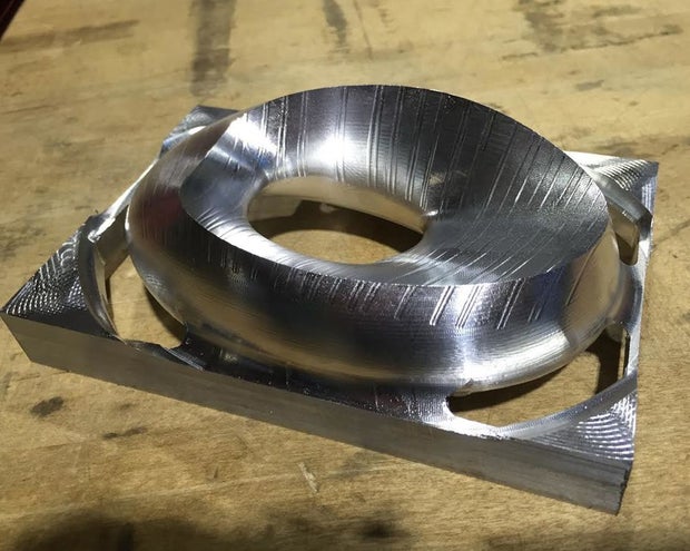
But what do you do when your shape is more organic or irregular, and also must be flipped to machine on both sides? In this case, you need to model additional material that will hold your part inside a vise, against a spoiler board, or flat against the bottom of the machine. It's very hard to program the CAM without having these features incorporated into your model.
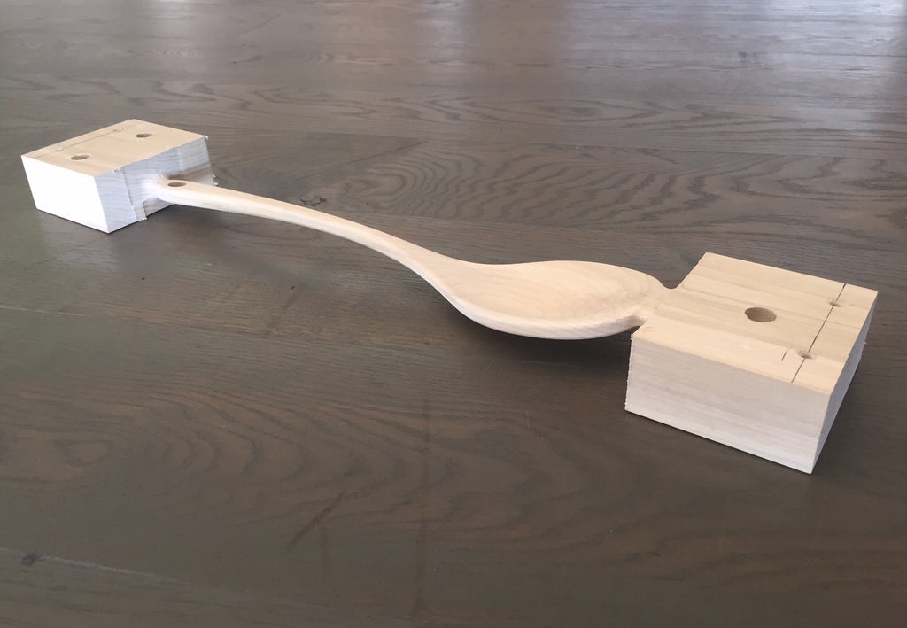
In other words, 3D flip machining requires that you model the stock you want left behind, as well as tabs to prevent your part from coming loose inside the machine. These tabs will be cut off and sanded down after machining, usually with a bandsaw and disk sander.

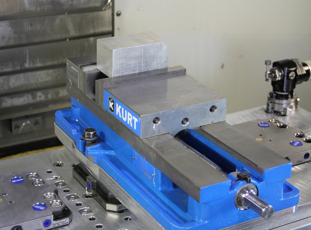
Note: Another, more advanced, technique for workholding for irregular shapes in metal is a soft jaw system. You would machine your own custom aluminum jaws to use with a Lang or Kurt vise, and these custom jaws would hold your part after the flip. No tabs needed.
For your serving spoon, you will have two tabs--one on each end--and a rectangular prism of stock that will hold the spoon flat after the flip. When modeling, it's a good idea to make your stock and tabs another body, separate from your part.
Step 4: Registration

Because the spoon will be machined from both sides (flip machining), you need a way to ensure that the CNC machine can locate the part accurately after it has been moved. This is called registration.
If you have used the Haas before, you're familiar with using a probe to locate your part . The DMS, however, like many table routers, does not have a probe. When using the DMS to locate the origin of your Work Coordinate System (Work Home), you will insert a tool into the spindle and jog it to the correct location. It's common to trap a piece of paper between the stock and the tool to ensure that Z is correct. In the DMS machine class you will learn how to enter the codes to set your WCS in this way. As you might imagine, this system is not accurate, because you're just "eyeballing" this location.
This means that if you have a part that requires flip machining, you need to consider how to get the two sides to line up properly with one another. There are lots of options, and they all have advantages and disadvantages based on the specifics of your part. Some common methods include:
--Attaching stops to your spoiler board (waste board under your part that can be machined) or machine bed
--Machining a contour into your spoiler board, then placing your stock exactly inside that contour
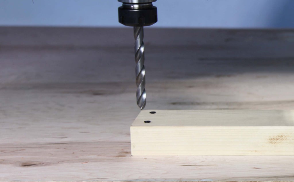
--Drilling holes for dowels that go into the spoiler board beneath your part (most accurate)
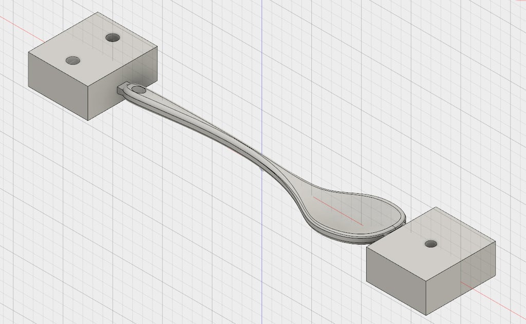
This final technique is the the method you will use for the spoon. While machining the front side of the spoon, you will also drill three holes through the stock and partially into the spoiler board. After you flip your part, you will insert dowels through the holes and into the spoiler board that will align your part perfectly with your first side.
Step 5: CAM Settings
The specifics of the project - machining wood on the DMS router - will also determine some of the choices you make when programming toolpaths.
-Tool numbering
If you are a Pier 9 shop user, you will be using the DMS tool library. When you have simulated and finalized your CAM program, make sure that your tools are labeled in the chronological order that they are used. You will learn later in this class how to edit tool numbers.
Remember that the chronological tool numbers in your program do not correspond to the numbers in the DMS tool library drawer. For instance, the fifth tool you use in your program might be the 1" Rough Short End Mill, which is labeled #34 in the DMS library. You will see the DMS library number in the comment for each tool, which will appear in your setup sheet (machining plan). You will learn later how to generate setup sheets.
If you are not using Pier 9's DMS, you'll either be using custom tools, or tools from your own tool library. If using your own library, be sure to label your tools in the chronological order they will be used.
-Rules for roughing
Machining in wood or plastic on the DMS is not high speed machining (HSM). This means that you may use Adaptive toolpaths for roughing, but you cannot use the whole length of the cutter.
When machining wood or plastic, follow the Stepover and Stepdown Rule: The stepover and stepdown should never exceed 50% of the tool diameter.


