

Introduction: Mad Scientist´s Ionizer, a Steampunked Beacon Light for Time Travellers


Hi everybody!
Last year I got into contact with the famous neon-glass-blower Roger Jürs, Hamburg who creates neon signs for more than 20 years.
And some months ago he surprised me with four small gas filled tubes which he blew for me especially for testing them with my favourite flash units of disposal cameras and as well with some different modified hand cranked voltage generators / inductors, which I built from very old electrical insultation testers. (I will write a separate instructables about it later) and in case of success he asked me to create steampunk objects with them.
Roger used very rare brown coloured glass tubes 18 mm in diameter and filled one tube only with pure neon gas and three others with a mixture of 75% neon 25% argon and an very small drop of mercury. This dark brown colour supports the red colour of neon very well and the blue colour of the gas mixture changes through this brown filter into bright green light. Well I succeeded and here comes the first result of my efforts.
I now proudly present the „Mad scientist´s ionizer, a steampunked beacon light for time travellers" to you.
This light stand is also very suitable to explain and test the behaviour of noble gases in Physics education at school. All important parameters can be measured and testetd by the pupils.
Please take first a look at this video other small videos will follow at the different steps.
Please note!
In this project it is really important to take care about your health. Dont wreck it! Use safety gloves, eye protection and even ear protectors if necessary when you work with machines, sharp metal parts, or glass. Take also care and obay the technical rules when you are working with high voltage! See also this tutorial .
And now let´s start with the description of the making. I hope you enjoy it and if you like it please vote for it at the „make it glow contest“.
Yours Aeon Junophor
Supplies


It is one of my principles to work with already used parts or things from the scrapyards so it is very difficult to name links but it is always up to your own creative ideas which parts do you choose if you like to rebuild this item.
I took:
1 pc glass tube, filled with neon gas or mixture of other noble gases, 18 mm in diameter, length about 18 cm
2 pcs plywood plates 17 and 15 cm in diameter
1 pc ball bearing cage(cage) made of laminated fabric 15 cm in diameter
1 pc peforated plate made of copper
1 pc one-handle built-in mixer made of brass from the scrapyard
1 pc brass rod ø10 mm, length about 50 cm
8 pcs screw anchor M4 (brass made)
8 pcs screws M4 60 mm (brass made)
8 pcs washers (brass made)
4 pcs screws M5 x 25 (brass made)
4 pcs nuts M5 (brass made)
4 pcs washers (brass made)
different brass made T- fittings, threaded rods, pipe fittings, nuts, screws and bolts from srap
15 mm coppertube from scrap
4 pcs 90° fittings copper tube 15 mm
2 pcs copper tube bows 180° 10 mm in diameter from scrap
6 pcs pieces of „munsen-rings“ 35 mm in diameter,
1 pc munsen-ring 15 mm for the top of the stand
1 pc uranium glass marble for decoration ø 15 mm,
2 pcs acylic glass tubes 40 mm in diameter inside 34 mm inside, length about 22 cm
4 pcs cap nut, brassmade ø 40 mm
two pairs of very old power resistors (in fact they are ceramic tubes enwinded with wire and then laquered),
copper made washers and brass made screws M3 for decorative filling of the tubes,
also threaded rods M3, length about 28 cm
some plates of red fiber for the caps some ball nuts M3 some copper made small sieves as decoration, and some small stripes of laminated fabric from broken ball bearings
2 pcs edison sockets E27 „centra“ - type
1 pc copper made tube 22 mm in diameter, length about 20 cm milled with a groove of 11 cm
1 pc acrylic glass tube 20 mm in diameter, length about 20 cm
different types of wire
various pieces of shrinkhose of different diameters
2 pcs banana-sockets 4 mm
1 pc three row minature switch
1 pc flash unit pcb of a disposal camera (Fujii quick snap)
1 pc piezo igniter from empty disposal cigarette lighter
1 pc battery-box
1pc 1.5 Volt AA battery
4 pcs device feet
Tools:
meter stick,
pencil
drilling press
cordless powerdrill
pliers
sharp knife
drills
sanding paper
woodglue
wrenches for nuts and bolts
screwdrivers
soldering iron
blowtorch to solder copper the tubes
vise and screw clamps
metal saw
lathe
router table
diamond drill ø10 mm
thread cutting die M3, M4, M 10
thread cutter M3, M4,M10
two component epoxy resin
hotglue sticks and hotglue gun
grater
jig saw
hole saw ø 45 mm
forstner drill ø 22 mm
pipe cutter
polishing solution for brass and copper
zapon laquer
line seed oil
acrylic paint, colour: black (shining)
Step 1: The Pedestal


Ancient tripod stands for chemistry or physics with their screw clamps and all the strange looking equipment have been the model in my mind when I started this project.
My idea was that the stand itself should look like it comes directly from the laboratory bench of a mad scientist and so the story began.
Strange old resistors raise up in their acrylic glass columns, pretend that they handle with high voltage things, have been placed left and right aside the main tube holding the neon gas filled tube. Several switches, push buttons and sockets for banana plugs are integrated in the pedestal.
First the two plywood plates were cut with a jig saw, then milled circular and contured with the router. Later they wer painted black with acrylic paint.
Between top and bottom plate a ball bearing retainer made of laminated fabric was placed an covered with stripes of perforated copper plate from the inside. Three of the cage holes were filled with the piezo igniting push button and the two banana sockets in their brass made holders. So a crank inductor can be attached with banana plugs to light up the neon tube.
The bottom plate of the pedestal got an integrated battery box to change the AA-battery easily from the bottom side. All parts of the pedestal were screwed together with eight pieces of M4 brass screws. That´s why I drilled brassmade screw anchors into the bottom plate. At the downside of the top plate I fixed the flash unit pcb with a screw and also drilled in the main switch.
The brassmade one-handle built-in mixer was fixed with four screws M5 to the top plate.
Step 2: The Brass Stand


The one-handle built-in mixer from the scrapyard was cleaned, polished, covered with zapon laquer and then modified in that way, that I screwed a closing cap ¾“ in the biggest threaded hole. In this cap I cut a thread M 10 in to screw later the brass made ø 10 mm rod in. This screw connection was fixed additionally with epoxy resin. Through the mixer lead some runners to a central outlet ,12 mm in diameter which I used as hidden wireways.
The other two holes on top of the mixer formerly provided hot and cold water tubes. In these holes ø 10 mm, the two 180°coppertube bows fit perfectly in. They now lead down to the Mixer footplate and cover there two of the holding screws. These bows were covered with several brassmade knurled connecting nuts just for desoration.
Two brassmade T-fittings with an inner diameter of 10 mm were used as the central tubeholders. I cut threads M8 inside the middle hole to attach there the munsenrings for the main tube. Outside the T-fitting other munsenring parts could be fixed with screws to hold the acrylic glass cartridges later.
A combination of four 90 degree bows of 12 mm copper tube fittings was soldered with a blowtorch and small parts of 12 mm copper made tube in that way, that they later lead to the center of the Edison socket. In this tube the connecting wires from the neon tube run down to the pcb of the flash unit.
Step 3: Beacon Light Tube


The tubeholder of the neon gas tube ø18mm itself had been constructed in that way that I first covered the glassmade tube with a small acrylic glass tube ø 20 mm which fitted then perfectly in the milled coppertube ø 22 mm. After soldering and insulting the wires to the contact wires of the neon tube, the enclosing acrylic tube was sealed with hot glue at both ends. Inside this tube a very small wire -insultated with silicone- lead down from the top contact at the backside of the neon tube. This construction was then covered with the coppermade and milled shield tube. At least this tube was combined with the „E27 – centra type“ Edison sockets using small plywood slices glued with red fiber.
One of these edison sockets, the one which is connected to the downleading copper tube bows, got in its foot contact a hole ø10 mm for the wires which I drilled very carefully with a diamond drill. I needed a lot of water for cooling and mainly to prevent glass dust. Please wear a dust mask and safety eye protection while drilling this.
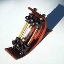
Step 4: Resistor Cartridges


For a real working "Mad scientist´s ionizer, a steampunked beacon light for time travellers" you need some power resistors to neutralize disturbing energy beams from landing time travellers to avoid damages.
Such very old power resistors often had been built in that manner, that ceramic tubes were enwinded with a special resistor wire named „constantan wire“ and then laquered. For heat protection they had been screwed on a threaded rod which then was fixed to the casing. Well I did it nearly in the same way by using a very long piece of 3 mm threaded rod put the resistors on it with other decorating elements of copper made washers brass screws and nuts M3 as well as selfmade nuts with M3 thread cut in two directions. Therefore I used already drilled brass parts from clock making manufacturers which only needed the right thread cut. I also added some stripes from small broken ball bearing retainers -also made of laminated fabric and fixed them with screws. These stripes are a little bit flexible and keep the „resistor-column“ right in the middle of the acrylic glass tube. The acrylic glass tubes were at least closed with brass made knurled caps keeping a slice of red fiber and screwed with copper mades sieves for decorating and another type of hand crafted knurled nuts to the central threaded rod. Once screwed together thecartridges only needed to be attached to the stand each with a pair of munsenrings ø 35 mm which I carefully stretched to nearly 40 mm. This is a risky work and I have to say that three of these rings had been broken before I found out the right way to handle it......
Step 5: Electrical Equipment


If you know some of my other projects you might know the elements I used for this "Mad scientist´s ionizer, a steampunked beacon light for time travellers".
If not. I´ll explain it shortly. For further information you can read this tutorial.
Well, Immediately after getting the neon tubes I started my attempts and experienced that the ignition power of the flash unit is often too low to start the reaction with both types of filling gases. But if such a light-tube is once ignited the flash unit works very well.
After some research in literature about the electrical behaviour of noble gases, the idea came to my mind to use a piezo-igniter from an empty disposal cigarette ligther to give an igniting pulse to the noblegas in the tube. And it works surprisingly fantastic. You just have to start the flash unit circuit first and then give an ignitnig pulse and that´s it. Therefore it doesn´t matter if the piezo igniter is part of the electric circuit or just nearby the tube.
So I took one pcb of such a flash unit from a disposal camera, desoldered all parts which are´nt needed any more and soldered the pcb to wires leading to the neon tube . A three row switch was added to interrupt the pcb circuit (to avoid inadvertent circuits) when you want to use a hand cranked inductor to light up the neon tube separately. Therefore the inductor needs to get in contact with the banana plugs through safty wires.
When a noble gas filled tube shines, it behaves like a wire and so you need a small power resistor to avoid shortcuts of the circuit. I took one with 8.2 Ohms and 25 Watts. Because of the very low current of this "low-powered" system it is enaugh.
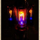
The piezo igniter is connected directly to one wire of the neon tube after the main switch so you can give a pulse when ever you want and you can also show in that way the igniting pulse itself as a short flash.
The following video shows the circuit basically without any decorating elements. I am sorry about the age restriction but you will see that some wire connections in this video are not insulated as necessary and might hurt someone who wants to copy this "unprotected" sample. My intention was to show the circuit basically, so please don´t wreck yourself and do not work with uninsulated wires and high voltages!!! Safety first!!!
Step 6: Research and Experiments


Here you can find further informations about the technical details of piezo igniters, noble gases and the technical use of commercial neon signs. If you follow this link,
https://www.hansen-led.com/know-how/neon
you will find some more very detailed informations about the most important electrical aspects of neon signs. Some documents are already attached down below.
I n this project I also built another item which uses the glass tube filled only with pure NEON but technically it is built indentically to the construction of the "Mad scientist´s ionizer, a steampunked beacon light for time travellers".
There you can also see the flash light of the piezo igniting pulse very well.
For testing the modified cranked inductors, I took three different types with generating about 250 Volts DC (made by EAW-Treptow), 500 Volts DC (made by Siemens & Halske), 500 Volts AC (made by Gossen, called „Isognom“), and 1.000 Volts DC (made by AEG).
All of them were originally used to test the insulation of electrical installation with the resistance of 1 MEG Ohm. So they generate different amounts of current too. As a result of these tests I experienced that the inductors with more than 500 Volts output work well, the one with 250 Volts output is very often less powerful for igniting (You have to turn the crank very „speedy“ to light the tube up).
Well I hope you enjoyed this project and if you like it most please vote for it at the make it glow contest
At least I want to say good luck to all time travellers! This "Mad scientist´s ionizer, a steampunked beacon light for time travellers". will help you to find your way ;-))
Yours Aeon Junophor
Attachments


Participated in the
Make it Glow Contest


