

Introduction: Gingerbread Home Automation


Inspiration
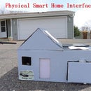
We had a gingerbread house building event at work over the holidays. I've never built a gingerbread house before, but I wanted to make one that's interactive. The idea is to build small Bluetooth sensors to put around your house (in this case, just on the front door). Then have the gingerbread house mimic what the real house is doing. For example, when the front door opens on your real house, the front door on the gingerbread house also opens. And to make it more festive, I added LED's that you can control from a phone app or via twitter. I wanted to use as much open source software as possible, including MQTT, Node-RED, and OpenHAB. Here's a demo video.
. . .
. . .
System Diagram
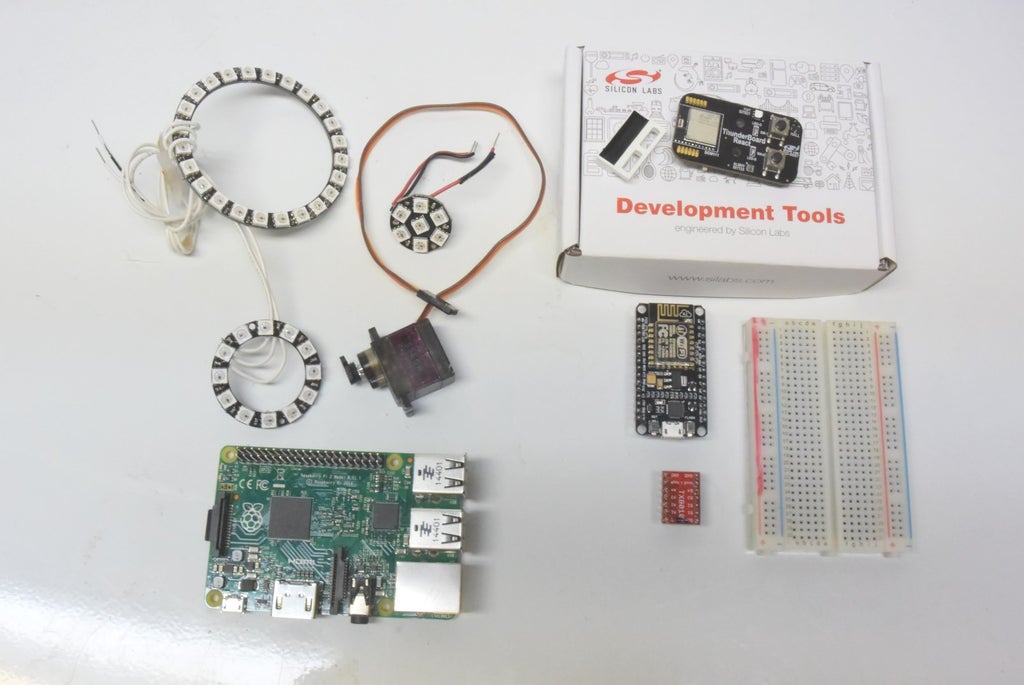
- (Inputs) BLE Sensor This is a Bluetooth Low Energy (BLE) module from Silicon Labs. I mounted a magnetic reed switch to sense if the door is opened or closed. When there's door activity, this sensor sends the new door position to the gateway.
- (Outputs) ESP8266-Powered Gingerbread House: I'm using an ESP8266 WiFi module to control the gingerbread house LEDs and front door servo motor. The ESP8266 gets door positions and LED colors by subscribing to MQTT topics.
BLE-MQTT Gateway: In order to bridge the BLE sensor with the WiFi gingerbread house, I made a BLE-MQTT gateway. This gateway has two components. A BLE module to capture the sensor data and a Raspberry Pi to publish the sensor data to MQTT.
The Raspberry Pi is also running OpenHAB and Node-RED. I'm using OpenHAB to provide the mobile app functionality to remotely monitor the door status as well as change the LED color on the gingerbread house. Node-RED is used to interface with Twitter or send text messages. So you can change the LED colors via Twitter tweets, and receive text messages if your basement gets wet.


. . .
Thunderboard React BLE Module

The Thunderboard React is a development board from Silicon Labs. It's has a Bluetooth Low Energy module (BGM111), with some of the I/O pins broken out to through-hole pads to which we can solder sensors. It's powered by a coin cell battery and comes with two on-board buttons and LEDs. Most useful for us is the small size and good range. It has enough reach for home automation projects, and it's small enough to be useful for making sensors. This Thunderboard React module is used for both the sensor and the gateway.
Network
I wanted to set it up so the gingerbread house doesn't need to be on the same local network as the bluetooth sensors. I wanted to be able to put the BLE sensor and gateway in one house, and have the gingerbread house far away, but still have it do that door thing.
. . .

...

. . .
BOM
BLE-MQTT Bridge
Sensor
Gingerbread House
- ESP8266 wifi microcontroller
- Level shifter
- MG90S Servo motor
- WS2812 LED ring, 12
- WS2812 LED ring, 24
- WS2812 LED singles (qty 8)
Software: Github Project. The different pieces of software are explained throughout the project.
Building this is pretty much like any other electronics project. Download the code onto the microcontrollers, and wire up the LEDs and servos shown in the wiring diagrams. I hope my explanations of how it works is detailed enough for others to modify for their needs.
Step 1: Build the BLE-MQTT Bridge


The BLE-MQTT bridge is probably the most complex part of the project, so I wanted to explain how it works in detail.
In order to translate the bluetooth sensor event into something the wifi module can see, we need to bridge the two protocols. That's what this BLE-MQTT gateway does. I'm using another Thunderboard React module as the BLE scanner. The BLE scanner is constantly scanning for our BLE sensor data advertisement. When it sees one, it then looks for the characteristic we've defined in the sensor and reads that data, and spits that data out on the UART.
The UART data from the BLE scanner is in the format
TTTTTT M
Where T is the Bluetooth sensor's 6-byte MAC address, and M is the sensor data. This diagram explains it better.

The Python script on the Raspberry Pi monitors the UART receive pin. It expects this format, and pushes this data onto the IP network using MQTT. This gateway basically breaks the BLE data out onto the LAN, allowing the WIFI module to see the data.
The Raspberry Pi is also running OpenHAB, a platform that provides the phone app functionality. OpenHAB is using the same MQTT mechanism to communicate with the gingerbread house wifi module to change the LED colors. When you use the app to change the LED colors, OpenHAB is publishing the Red, Green, and Blue (RGB) values via MQTT. Similarly, OpenHAB is monitoring the door sensor MQTT topic, and updates the phone screen's "Front Door Is" status accordingly. I'm not sure it makes any sense to use the phone app to manually open/close the gingerbread house door, but I wanted to document the mechanism for doing it.

. . .
Software
There are 3 pieces of software needed on the gateway. They're all in the same project on my github account.
- BGM111 gateway code for the gateway BLE module.
- Python script
- OpenHAB configuration
You'll need to install Mosquitto, the MQTT broker, on the Pi.
sudo apt-get install mosquitto mosquitto-clients python-mosquitto
Run the Python script in the back ground.
nohup ./ble_gateway.py &<br>
Download the OpenHAB runtime. Replace the demo configuration with the one listed above. This is a bit of a simplistic description, but I'll leave the detailed explanation on running OpenHAB to their wiki. OpenHAB is not needed to get the sensor to open and close the gingerbread door, but it's needed to change the LED colors.
Build
To build the gateway, start with loading the gateway firmware onto a Thunderboard React module. You'll need to use the development kit listed in the BOM. There might be a cheaper way to program this that I don't know about, but this kit is the official method.

Use this "QSG108" quick start guide to get started with BGTools. Basically, you want to open up the gateway project file linked above with BGTools, compile it to generate the .bin file, and then download the .bin into the Thunderboard React BLE module using a separate program called Simplicity Commander or EA Monitor (this comes with the BGTool install). If you have trouble, Silicon Labs forum is a good place to search or ask questions.
Once the module is programmed with the gateway code, follow the above wiring diagram to connect the BLE module to the Raspberry Pi 2. My setup uses the Pi 2 because of the free hardware UART. If you're using the Pi3, you'll need to enable the miniUART. Also note that the Thunderboard React module has a switch that selects between battery and external power. It should be switched to use external power, as we're powering the module from the Pi's 3.3V supply.

I mounted the module like a beanstalk on the Pi, using a zip tie and sticky to hold it up. Placement of the gateway is somewhat important. You'll want it centrally located to provide as much coverage with a single gateway as possible, otherwise you might need to build another gateway. The BGM111 part in the Thunderboard React has pretty good output power while still managing to run off a coin cell. With one gateway, I'm able to reach all of my three bedroom house.
Step 2: Build BLE Sensor


The sensor is just another Thunderboard React board. Compile and program the sensor module using the instructions found in the gateway step, but use this sensor code here. The sensor uses a simple reed switch connected between one of the power pins and pin PD13. That's it, the wiring is pretty simple. Don't forget to move the switch to VBAT so that the battery is powering the module. The code turns on the LEDs so you can see when it's transmitting and connecting to gateway. Comment these lines out when you're confident things are working.
Once the module is programmed and the reed switch soldered, the BLE sensor can be placed in an enclosure and mounted on the door. Attach magnet to the door.
When I tested the range on these modules, I was able to reach all of my house when the gateway somewhat centrally located.
Step 3: Gingerbread House Build!


This is the fun part. Here's some progress pictures of how I built the gingerbread house. Tailor this to what you have available. This was my first gingerbread house, and after seeing what other people can do, I admit the aesthetic portion of my build was pretty mediocre. Next year, more icing and decorations!
Cutting The Door / Window
I used a dremel to cut the door and window openings, as well as the USB cable opening in the back of the house. It worked surprisingly well, it didn't crumble. The heat from the dremel tool kind of cauterizes the cut surface of the gingerbread, so that was mildly interesting.
LEDs
The roof LED is a series of 8 individual WS8212 soldered together into a V shape. I liked the way they looked when covered with frosting. I did check to make sure the frosting isn't conductive before slathering it on the bare LED contacts.
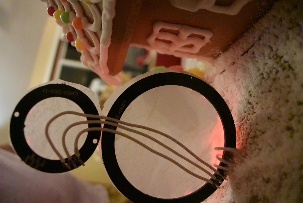
The snowman is a 12-led ring and a 24-led ring of WS8212s wired in series. It's hot glued to the tray so it stands upright. I used parchment paper and glued it onto the rings of LEDs. Finally found a use for that ten year old parchment paper.
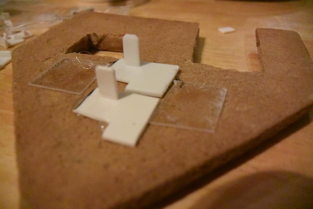
Front Door
Making the front door was tricky. I made a friction-fit bracket for the servo motor using...stuff. Well, it's the plastic safety cover from one of those cheap extension cords. Feel free to improvise, as I was just looking around for anything that might work. I used hot glue to attach the bracket to the gingerbread. That worked surprisingly well as long as the surface area is large. The actual door is just a piece of stiff paper from junk mail hot glued to the servo arm.


Step 4: ESP8266, LEDs and Servo


The ESP8266 connects to the MQTT broker on the Raspberry Pi to determine the colors to display on the LED as well as how to position the front door servo motor. The ESP8266 code is here. I'm using the NodeMCU version of the ESP8266. A couple of items that need to be edited is your unique wifi credentials and your Raspberry Pi MQTT broker IP address.
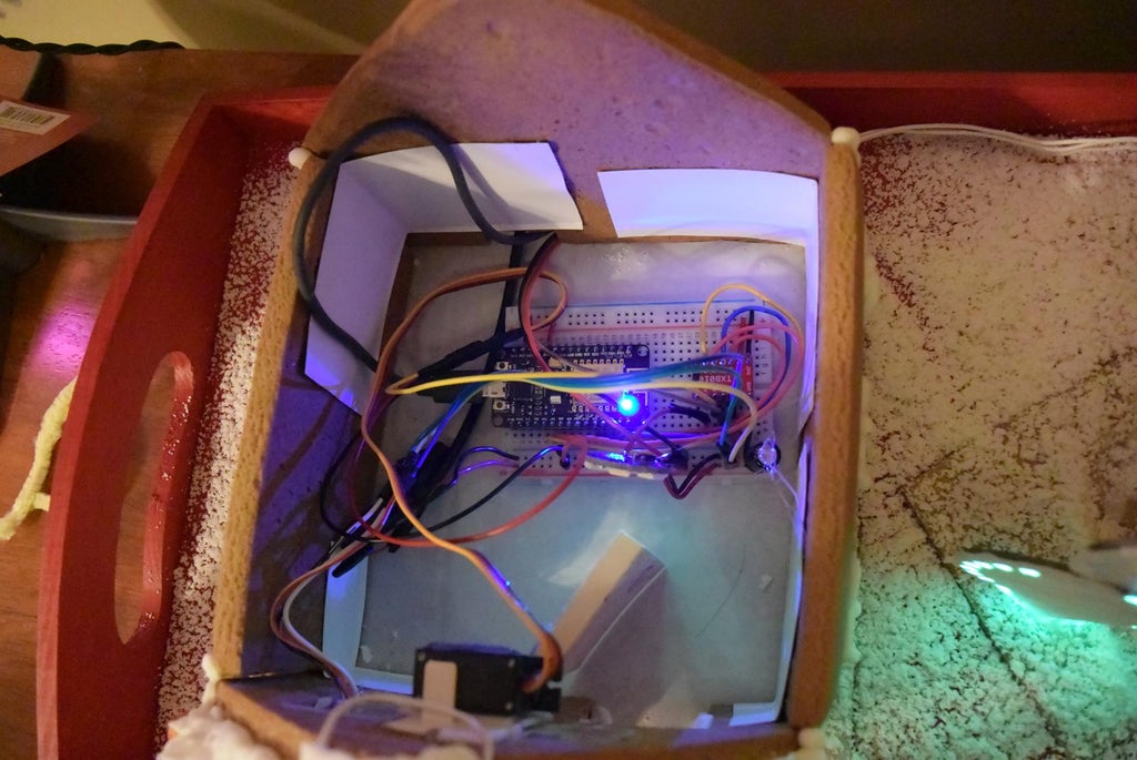
The microcontroller and breadboard is inside the gingerbread house, with two USB cables hanging out the back of the house. You'll need two USB cables. One of them powers the ESP8266 (I left that out of the wiring diagram because it obviously plugs into the wifi module). The other USB cable provides the 5V power rail for the LEDs and servo motor. The ESP8266 can't provide enough current for all the LEDs and servo. The signal from the ESP8266 runs through the 4-channel level shifter to the LEDs and servo. I did put a capacitor on the 5V power lines, but it's not really necessary because there's enough capacitors in those USB chargers, so I left that out of the schematic.
Here's a short clip of the servo motor turning the door, just to give you an idea of how to position the servo.
Step 5: Node-RED Adds More Connectivity


Because both the sensors and the LEDs and motors are all running on MQTT, it's really easy to use Node-RED to add more connectivity to the gingerbread house. There is already a MQTT node that allows you to subscribe and publish to the MQTT broker on the Pi. There are also email and Twitter nodes. We can use Node-RED to allow tweets to change the color of the gingerbread house LEDs for example. We can also use tweets to open and close the door, although this kind of detracts from the usefulness of the front door on the gingerbread house. But the point is that you can :)
The top section monitors tweets and parses out the text in the tweet to see if it's a color (and what color). It then publishes to MQTT the RGB value corresponding to that tweet color.

We can also have the door sensor post tweets when the door is opened or closed. The second flow monitors the MQTT message corresponding to the Bluetooth door sensor and tweets it out.

All the Node-RED flows can be found here. You can just copy the text and import it into your flow.
Step 6: Making a Water Leak Sensor


That's it for the gingerbread house. But I wanted to make one more sensor. It's great to have the flexibility to make sensors to do what you need. The same door sensor can be used to make a water leak sensor that'll text message you when water is detected.
. . .
. . .
The picture gallery pretty much describes how to make the sensor. But for completeness:
- I used the exact same circuit as the door sensor, but instead of a reed switch, I used two wires on the power and PD13 pins. These act as water probes.
- Drill holes for the wires to come out of the box.
- Attach foam to the bottom side so it can float if there's a lot of water. I'd like to save the sensor as well as the basement.
- Use this Node-RED flow from the previous step, the sensor is included in that flow. There's many options for how to get notifications. Email and text message makes more sense than Twitter. For text messages, I'm using Twilio to get the responsiveness, but email would work pretty well too.
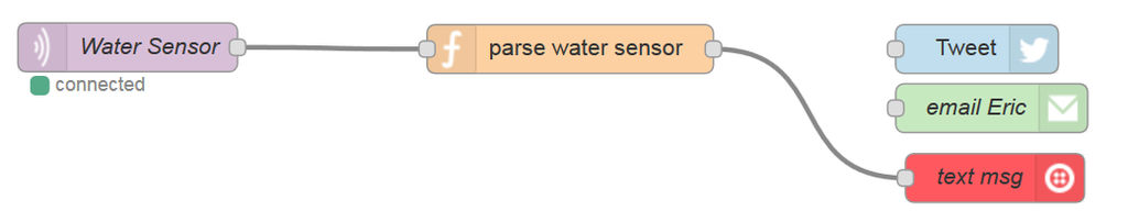
I have reservations about how well this circuit works under all conditions. If you have lower levels of mineral deposits in your water, this may not work as well. But I wanted to show the flexibility of these DIY BLE sensors when combined with a cool platform like Node-RED.
The video was shot in the basement laundry room. The gateway is sitting upstairs by the router, just to give some idea of the range.
Step 7: Happy 2017


:)

Third Prize in the
IoT Builders Contest

Participated in the
Make it Glow Contest 2016

Participated in the
Arduino Contest 2016


