

Introduction: Tweeting Pregnancy Test


The project idea came from this tongue-in-cheek twitter post. But hey, why not try to make one? I read somewhere that the world needs more ridiculous smart devices. So here it is.


I’ve (we’ve) only ever used the non-digital pregnancy tests where you read the strip. So to gauge how easy it is to hack the digital pregnancy tests, I googled the customer service number for one and proceeded to quiz the nice English lady on the other end of the phone.
Does your test have an ON button? What kind of battery does it use? Do the different characters on the LCD overlap, or are they separated? Well, I mean, is “Pregnant” the same as “Not Pregnant”, but just without the “Not”? You need a serial number? No, I don’t have a serial number, I haven’t purchased it yet. Oh...well, I like to be prepared.
So that didn't work, but it turns out you can learn a lot about pregnancy tests from youtube. There are lots of youtube videos of “live pregnancy tests”. Go ahead, youtube it, I’ll wait.
Now that we’ve all re-calibrated for what’s normal, this project doesn't seem weird at all. It's interesting to take apart a pregnancy test to see how it works.
Step 1: How Pregnancy Tests Work


See the above photos for an explanation of how this Target brand pregnancy test works.
- Sample Transport Media - absorbs the sample and transports it up to the rest of the device.
- Metal Gap of Turning On - the sample travels upwards from the transport media, and it bridges this gap. The ions in the sample creates an electrically conductive path across this gap, and wakes the pregnancy test microcontroller.
- Chemical Test Strip - reacts with pregnancy hormones to create visible color lines.
- Vitamin - reward for those who take the thing apart.
- Two Photodiodes - light sensor that reads the test strip to determine if lines indicate pregnancy. Each photodiode has a red LED associated with it. Interesting that there’s actually a third LED in the middle that's not associated with a light sensor. The plastic shell creates an isolated cavity so each sensor sees only a certain portion of the strip. Perhaps the design is for more expensive 3-photo cell models?
- LCD display - displays the results “Pregnant”, “Not Pregnant”, “book”, and “hourglass”
These tests are one-time use products. The chemical strip isn't reusable, so once the device is activated, it won't ever work again. Removing and replacing the battery puts it into an unrecoverable disco mode, even if it has never been activated.
Step 2: How LCDs Work

The disco mode was pretty handy for figuring out which pin on the LCD displays which icon. I was kind of naive thinking that a high level on a particular LCD pin turns on a particular icon. I learned that LCDs don't work like LEDs, they need to be driven by an AC signal.
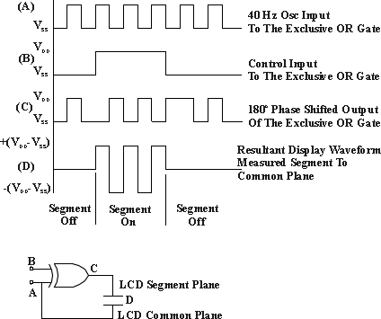
Source: http://www.lxdinc.com/application_notes/lcd_direc...
The pins that are easily accessible on the pregnancy test LCD are on the output of the XOR. So when the icon is on, that pin sees the half cycle phase shifted output relative to the regular "clock" waveform. With the unit in disco mode, it was easy to identify the clock pin (A) as well as the individual icon pins (C).

From this, I can see that when the icon pin is in phase with the clock pin, that icon is not being displayed.

However, if the icon pin is not in phase with the clock pin, the icon is being displayed, like the condition below.

Since I only intend to monitor the "Not" and the "Pregnant" icons, I only need 4 wires: Not, Pregnant, Clock, and Ground. I'm using a Light Blue Bean for the microcontroller, which also has a Bluetooth Low Energy transceiver.

Step 3: Prepare Pregnancy Test


Now that we know which pins we want to bring out of the pregnancy test, we need to solder the pins and wire them up to headers.
1. Drill holes into the top of the pregnancy test for the headers pins.
2. Solder 26 AWG wire to the headers.
3. Pull the wires through the holes and solder them onto the LCD pins found in previous step.
4. Reassemble the components. Cut the little bit of plastic above the LCD pins so that the wires aren't pinched.
5. Cut away more plastic on the other half of the shell to accommodate the wires.
6. Put it all together. Use hot glue to attach the headers in place.

Step 4: Prep the Bluetooth Module


The pregnancy test attaches to headers on the Light Blue Bean. The circuit above shows how it's wired up. The resistors on the ground are pull down resistors and the resistors on the I/O pin prevent too much current flowing back in case the Bean's battery is left out when attached to a powered pregnancy test. I used 1/8W 10k Ohm resistors so they fit nicely on the prototype area of the Bean.


To preserve power, the Bean is sleeping most of the time. Pin 0 on the Bean (connected to the clock pin on the LCD) is set as the interrupt to wake the Bean from sleep. When the test is not being used, there is no signal on the clock pin. When the test is activated, the LCD starts displaying the hourglass icon, and the clock pin is driven with the 40Hz square wave. This wakes it up.
The Bean also has a tri-color LED and accelerometer. I used the LED to indicate state:
- Wake-up blink: Upon wake-up, the Bean LED blinks green if Bluetooth connection has been established, and red if not.
- Testing: displays the "breathing" blue pattern. This phase lasts 1 to 3 minutes, depending on whether it's a positive or negative sample. The manual for the pregnancy test also indicates that the tester should not be place upside down. The accelerometer is used to check the direction of gravity during the testing phase. If the test is held upside down, the breathing blue pattern changes to a solid blue as a warning to the user that something is wrong, and perhaps qualify the test results. But mostly because I wanted to use what's available on the board.
- Result: Once the result is read, the data is sent via the Bean Serial to the Raspberry Pi for social media consumption. The LED also changes state. A solid red means not pregnant, solid green means pregnant.(4) Sleep: The Bean goes to sleep 8 seconds after it's unplugged. LED goes dark. The Bean module can be removed and snapped onto another test over and over again.
Bean program:
https://github.com/tsaitsai/Connected-Pregnancy-Test/blob/master/Connected_Pregnancy_Bean.ino
Step 5: Prep the Raspberry Pi


The Bluetooth LE (Bean) communicates with the Raspberry Pi via a USB bluetooth adapter. I'm using NodeRED to receive the Bluetooth data, and then Twilio and Tweeter nodes to send text messages and tweet. See above for the small bits of code for each node.
I happen to have some lights that are controlled via MQTT and OpenHAB. In the demo video, you can see the table lamp turn on when the result is "Pregnant". The lamp turns off when it's "Not Pregnant". The function looks like it's not doing anything, but it is necessary due to some oddities with OpenHAB not catching MQTT publishes without \n. The arrangement of makes it easy to visually exclude messages from different services.


Step 6: Tweet

In other news, my wife and I are really excited to be expecting our second child later this year :)

Participated in the
Arduino All The Things! Contest

Participated in the
Full Spectrum Laser Contest 2016


