

Introduction: Miniature Weather Station - ESP8266


Hi and welcome to an instructable about a miniature weather station.
The idea and much of the code is from a blog by Daniel Eichhorn at this web address, go check it out as he is into some cool stuff!
http://blog.squix.ch/2015/12/esp8266-weather-station-new-version.html
I have updated/changed the code for my use so that it works with a larger OLED with a different chipset (SH1106 vs SSD1306). I also added some new features and enhancements.
First things first, (if you haven't already), please watch the 2 minute video to see what it does...
...OK, now you have seen the video you can see that it:
1) Is a weather station which grabs data from the internet to show current conditions and a 3 day forecast
2) The unit can be toggled to show data in another city - perhaps where your relatives or friends live
3) The unit has a senor so can display the temperature and humidity indoors
4) The program will put the system into deep sleep after about 10 minutes and can be woken up by pressing the button on the top of the unit.
NB:
This build details the build of a 1.3" screen based unit although I have also made a 0.96" version. It was however very difficult to pack all these features into a 0.96" housing so I'm only detailing the larger build here.
Step 1: Materials Required & Circuit Diagram


Apart from the 3d printed housing, the 2 main parts you will require are:
1) ESP8266-12E Wifi board
2) 1.3" OLED (or a 0.96" OLED) if you are making the smaller version)
in addition the following items are required:
3) DHT22 Temperature and Humidity sensor
4) Momentary Push Button
5) Shock/Vibration Sensor
SW-18020P Electronic Shaking Switch Vibration Sensor
6) USB socket and a 5v to 3.3V Regulator
7) Some 10k resistors (I used a combination of surface mount and wire type).
Step 2: A Side Note on OLED Screens

Over the past year or so I've experimented quite a bit with these OLED screens. Whilst not part of this build I thought I'd write down a few thoughts/findings - skip this step if your only following the build.
OLED screens come in all shapes and sizes but currently there are 2 very popular ones.
1) 0.96"
2) 1.3"
They also come in 2 common colours
1) Blue
2) White
The chips that 'drive' the OLED are one of 2 flavours. The 2 chips are have many set-up commands that are very similar (or the same in most cases) BUT the set of commands used to display the information is different and so you can't just swap screens around - you need to change the program/library to suit the chip!
1) SH1106
2) SSD1306
I've uploaded 2 versions of the weather station software 1 suitable for the SH1106 chip and the other for SDD1306 chip.
The way that the chip receives the data can be one of 3 flavours
1) 2 wire I2C
2) 3 wire SPI
4) 4 wire SPI
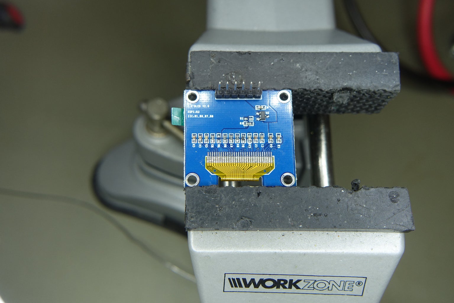
The advantage of SPI over I2C is that it is faster to write to the screen the disadvantage is that it takes more GPIO pins to drive. In this project speed is not a concern and so it is much easier to use I2C. Some displays (shown in the photo's above) can be configured for either SPI or I2C. I have done this but I'd highly recommend you get a display with ONLY I2C as I've spent many fruitless hours moving smd resistors around and trying to get a display that is delivered to work as SPI to then work as I2C. I did manage to get them to work (in most cases) but it took sooooo long I'd hate for you to get into a similar pickle!
Step 3: Adding 10k Pullups for the ESP8266 Chip


For the ESP 8266 Chip to work properly a number of pull-up and pull-down resistors have to be added to the board. This first step adds a 10k SMD resistor between GPIO 15 and the GND. I used a surface mount resistor as it fits nicely between the two pads, however it is fiddly to attach and you might prefer to use a wire wound resistor similar to the ones I used in the following steps.
GPIO 15 Pulled LOW = Normal boot-up, IE boot from the SPI flash memory on board the chip
Step 4: Add a Pullup Resistor to REST (the Reset Pin)

In this step I have added a 10k pull-up resistor from Vcc to the RST pin (the reset pin).
This will allow us to re-awaken the ESP8266 chip after we send it into a deep-sleep.
If you want to omit this function (and the associated momentary push button on the top of the case) then that's OK, just skip this step
NB: You will need to modify the code slightly just to remove the deep sleep function:
Step 5: Add a Pull-up Resistor to the Cip Enable Pin (Vcc - CH_PD)

Another 10k wire wound resistor is added from Vcc to the CH_PD pin which is the chip enable pin.
Step 6: Add a Pull-up Resistor to GPIO 0(Vcc to GPIO 0)

Another 10k wire wound resistor is added from Vcc to the GPIO 0 pin which is required to be HIGH for normal operation.
Step 7: Add the Final Pull-up Resistor to GPIO 2 (Vcc - GPIO 2)


Finally a 10k wire wound resistor is added from Vcc to the GPIO 2 pin which is required for normal operation
Trim the legs but leave 5mm stubs on the Vcc leg for future connections
Step 8: Start the Interconnecting Wiring
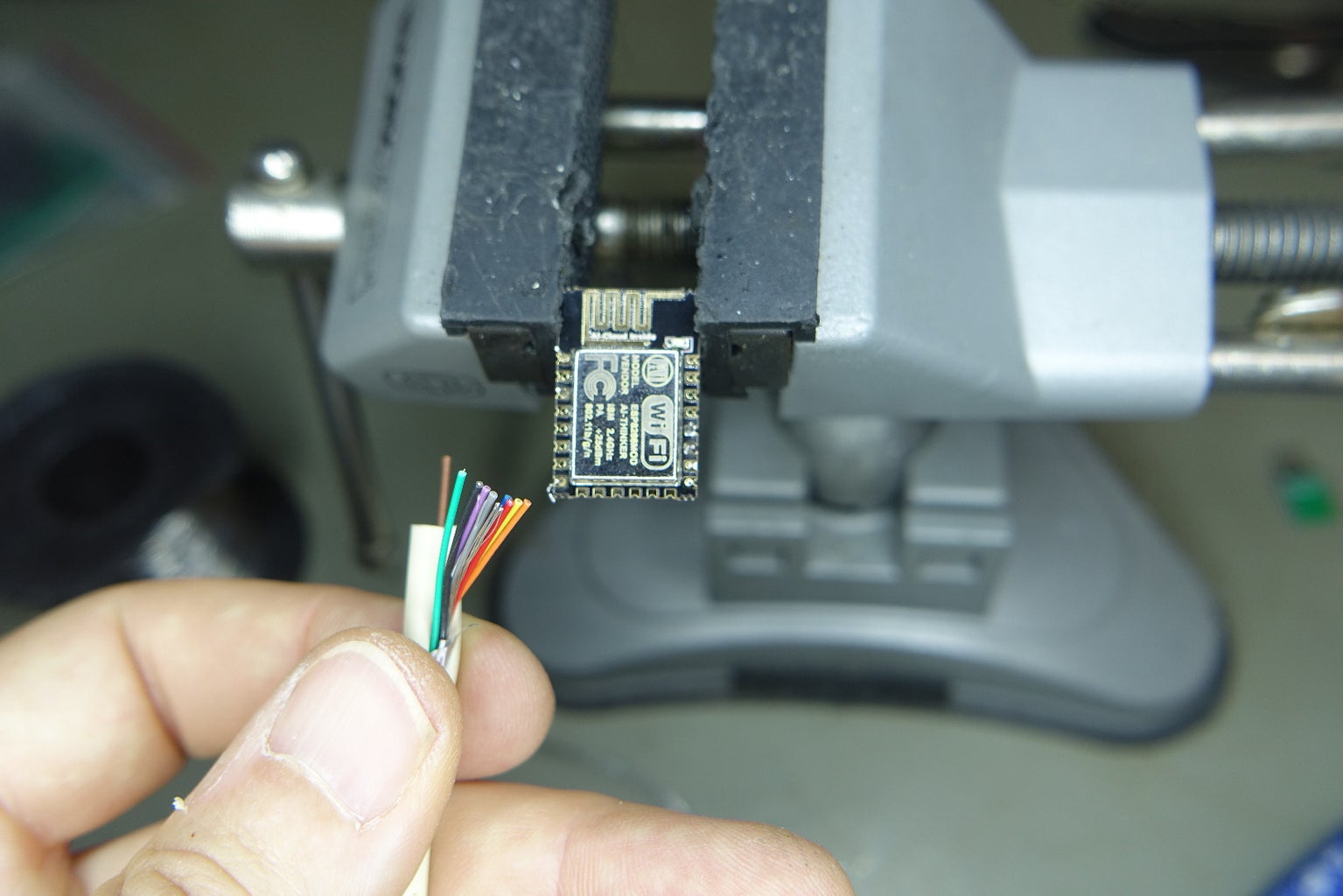
Now start to add some connecting wiring. You only need the finest of wires as the lengths are all short and don't carry much current.
I stripped the cores from a multi core cable which were nice and thin and flexible. Don't try to use thick 'chunky' wires as you will have problems later on when fitting it all into the very small housing!
Step 9: Start by Adding the Power Input Wires

Here I've added the +ve and -ve wires to the Vcc and GND pins on the ESP8266 (Red and Black)
Step 10: OLED Wires

Now add the 2 wires which will take the signal to the OLED (Orange and Green). The 2 pins to connect to are GPIO12 (Green) and GPIO13 (Orange)
Step 11: Add a Wire to GPIO 0

Add a wire to GPIO 0 (Blue). As you will see later this is required to program the ESP8266 chip. The GPIO 0 pin needs to be pulled to ground (LOW) when you want the chip to boot up in programming mode but held high when in normal operation. Just strip and tin the 'flying' end
Step 12: Add Wires for the Rx and Tx Lines

Here we need to add 2 wires to the Rx (Brown) and Tx (Grey) pins on the ESP8266. These are needed for programming and debugging with the wires going to the Rx and Tx of the FTDI programmer.
NB: the wires cross Tx to Rx and Rx to Tx
Step 13: Add a Wire for the SHT 22 Temperature and Humidity Sensor (GPIO 14)

Finally add a wire (Purple) for the SHT22 temperature and humidity sensor to GPIO 14.
Step 14: Prepare the OLED Screen
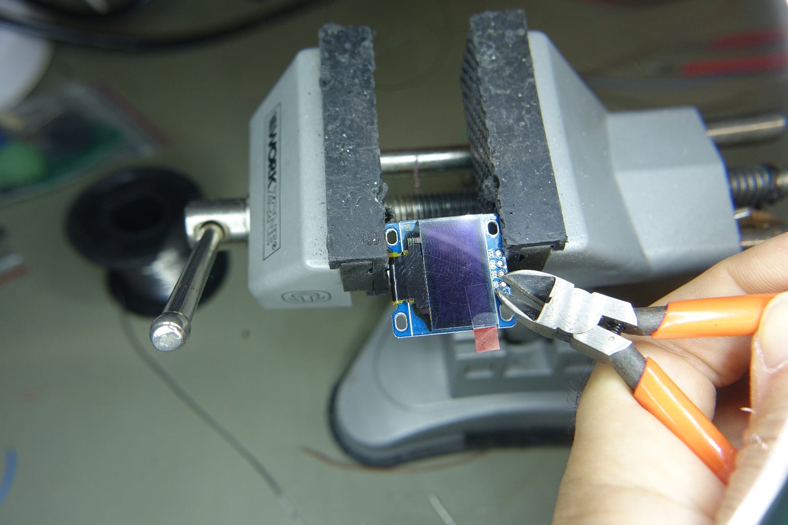
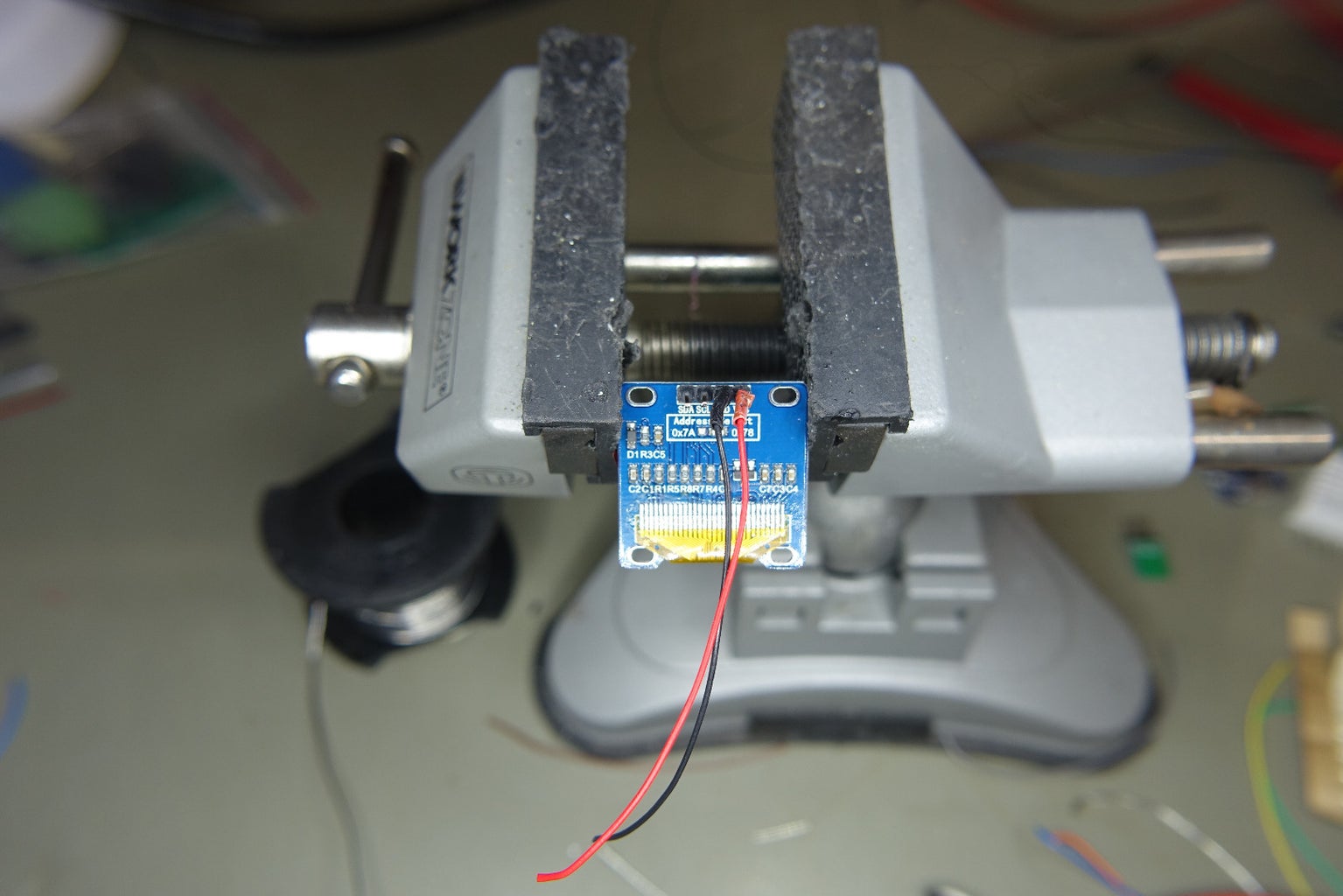
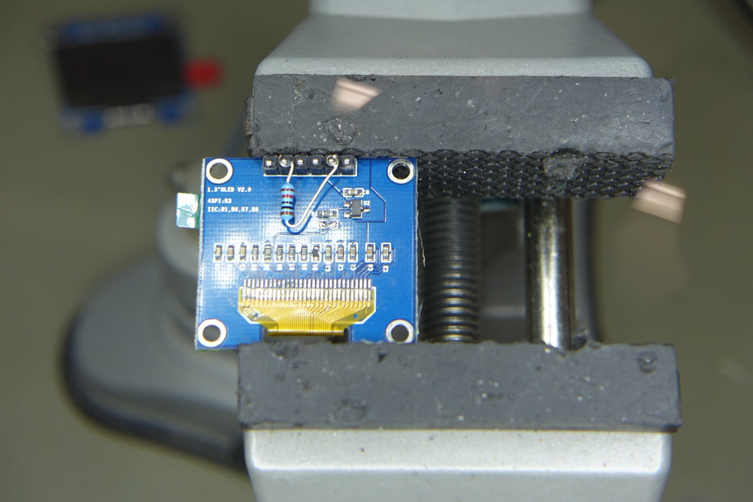
Before wiring up the OLED screen, trim the front side of the soldered pins. This ensures that they do not foul with the housing later when we install it. Also you can gently angle the pins so that it eases the installation into the housing.
Then add a Vcc and a GND wire (Red and Black)
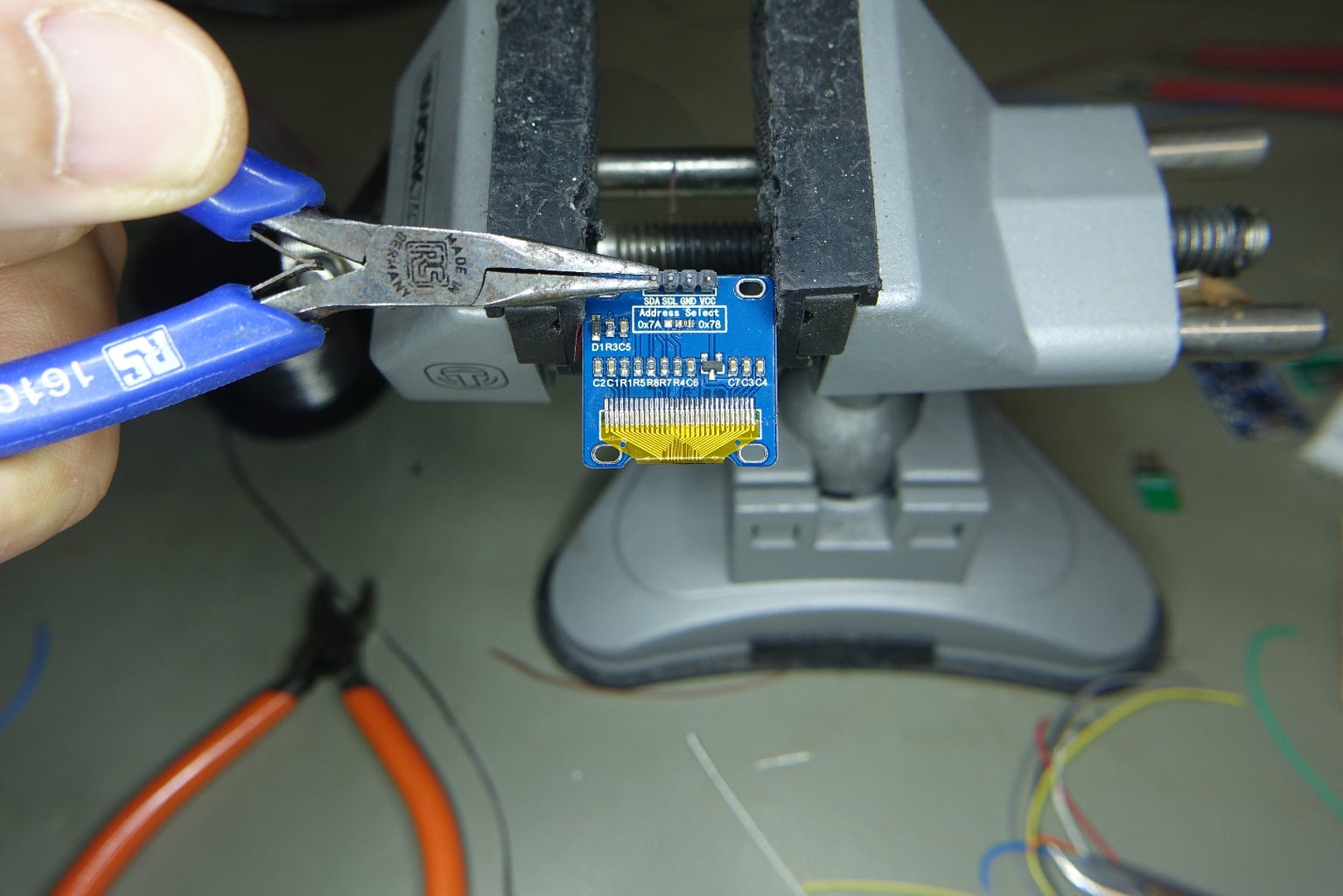
(I've shown a mixture of 0.96" and 1.3" inch screens in the pictures for this step. your screen may have different connections in a different order. As I said in step 3, it is best if you get a screen with only 4 connections, 2 for the power and 2 for the I2C - it will save potentially hours of wasted time. However, I've added one picture of a 1.3" screen which I configured for I2C by moving a link resistor and pulling up the RES line with a 10k resistor)
Step 15: Wire the OLED and ESP8266 Together

Wire the orange and green wires to the "Data" and "Clock" pins on the OLED display. Also twist together the Red and black power wires.
Pin 12 goes to SDA
Pin 13 goes to SDC
Notes for SPI/I2C screens (6 or 7 pin)
If your screen is not dedicated I2C then the connections may be marked as follows:
D0----------- SCL or CLK or SCK or Clock
D1-----------SDA or MOSI or Data
RES----------RST,RESET Rest Pull up this pin to Vcc with 10k resistor - also a 100nF capacitor is recommended to GND
DC-----------A0 Data/Command Ground This Pin
CS-----------Chip Select - Ground this pin
VCC----------3.3V
GND----------GND
Step 16: Add 2 Wires to the Shock/vibration Sensor

Add 2 wires (Yellow) to the shock sensor. Also add some heat shrink to this part as the legs are un-insulated.
Step 17: Wire the Shock Sensor in to GPIO 5

Wire the 2 legs of the shock sensor to GND and GPIO 5. It doesn't matter which leg goes to which pin, all the shock sensor does is short out the GPIO 5 pin and as such it is not polarised.
Step 18: The Software - Please Folow These Steps Carefully!

Even though this is not an Arduino based board we can use the Arduino IDE to program this chip
Rather than assembling the parts in the casing I think its best to test it 'as is' to ensure everything is working as expected. It is much easier to troubleshoot the device out of the box!
NB: this is based on the 1.8.1 Version of Arduino.
There are a few steps to take to ensure the software compiles and loads correctly I've tried to step through this carefully.....here goes
Part A - this is to set up the Arduino IDE to be able to program the ESP8266 module
Part B - This is to ensure you have all the libraries required for this program.
Part C - Modify the Arduino Program to add in your WIFI data and weather underground key
Part D - to load up the Arduino weather station program
NB:
Before moving completing Part C you will need to know some personal data like the SSID and Passphrase for your WiFi router. You will also have to get a weather underground 'key'. You can get a STRATUS key for free (limited to 500 calls a day) and can be got here:
General link to Weather Underground website:
Specific link to Weather Underground page to apply for a free key:
Step 19: The Software - Part A


If you have never used an ESP8266 then you will need to set-up the Arduino IDE to talk to this type of chip for the 1st time. If you've already done projects with an ESP8266 skip to the next step:
1) Open the Arduino IDE - I'm using version 1.8.1 at the time of writing this Instructable (Mar 2017)
2) Navigate to File > Preferences
3) Insert the following link in the "Additional Boards Manager URLs:" text box
http://arduino.esp8266.com/stable/package_esp8266com_index.json
4) Click "OK" to close the dialog box.
5) Go to the Tools > Board > Board Manager and click on this option
6) in the text box type "ESP8266" this should search and leave only one option "ESP8266 by ESP8266 Community"
7) Click the "more info" and then click the "Install" button that appears.
8) After the installation process completes (may take a minute or 2) you can press the "CLOSE" button to shutdown the dialog box
9) Go back to Tools > Boards and you should have some 'new' boards listed at the bottom of the list. Choose "Generic ESP8266 Module"
Step 20: The Software - Part B


Step 2 Add the necessary libraries
In addition you need to add some standard Arduino libraries.
You may already have then if you've done previous projects but I'll list them here just in case. These libraries can be uploaded using the the following steps:
1) From the Arduino IDE click Sketch > Include Libraries > Manage Libraries...
In the pop-up window use the search box to look for the following libraries (this uses your internet connection to get the files). Install them one after another
2) Type "DHT" library - this was already installed when I downloaded the IDE but you may need to add it
3)) Now Type "Ticker" library. This library allows timer functions to be called and was already installed in my IDE from the get go.
4) Now type "ESP8266WiFi " As the name suggests this is for the ESP8266's WiFi functions and again was already installed in my version of the Arduino IDE
5) Now Type "json streaming parser" - This is by Danny Eichorn and needs to be installed - Press the install button and wait for it to complete.
Step 21: Software - Part C

Firstly unzip the file attached at this step (chhose the one that matched your screens chip type, SH1106 or SDD1306) and open up the .ino file . There are 2 areas of the code where you have to add in your own personal data.
1) Your home WIFI SSID and password
On the WeatherStationInstructable tab find these lines of code and add in your own WIFI details
// WIFI
const char* WIFI_SSID = "Your SSID";
const char* WIFI_PWD = "Your Passphrase";
2) Your Weather underground key and the cities you want weather data from:
Adding in your own personal weather underground key:
// Wunderground Settings
const boolean IS_METRIC = true; const String WUNDERGRROUND_API_KEY = "Your WU api key";
String WUNDERGROUND_COUNTRY = "UK"; String WUNDERGROUND_CITY = "Leeds_Bradford";
// NB!!! - if the city has a 'space' in it ie Cape Town, use an underscore _
const String city1 = "Leeds_Bradford";
const String country1 = "UK";
const String city2 = "Sydney";
const String country2 = "AU";
Now save the changes and compile the program to ensure you have no errors.

Step 22: Software - Part D
Now load up the program to the ESP8266:
For this step you will need a USB lead and a FTDI programmer (3.3v version) and some temporary wires.
http://www.ebay.com.au/itm/like/142313799130?chn=ps
1) Connect the Tx and Rx of the FTDI to the Rx and Tx of the ESP8266 chip. (Tx to Rx and Rx to Tx)
2) Connect the ground wire from the FTDI to the ESP8266
3) Connect the USB lead to the USB port on your computer and wait for it to be recognized. Then in the Arduino IDE go to Tools > Port: and select the correct Com port for the FTDI
4) This next part is a little tricky as you have to power up the ESP8266 while grounding the GPIO15 line (with the flying lead added in step XX. This ensure that the ESP8266 boots up in a mode ready for data upload.
5) Now press the upload button in the Arduino IDE and watch the progress of upload which takes about 1 minute.
After the upload the ESP8266 will automatically reboot and you should have a working unit!
NB: OLED Screen addresses - IF YOU HAVE A BLANK SCREEN AFTER UPLOAD
After loading the software if you have no output on the display then the I2C address maybe different. There are 2 options:
1) 0x3c
2) 0x3d
Try changing this value where it is declared in the program on this line:
const int I2C_DISPLAY_ADDRESS =0x3c
...now try reloading the software again to see if it makes a difference.
Step 23: Prepare the Power Supply


As noted in the programming step the ESP8266 chip runs at 3.3v. As I want to power the device from the ubiquitous USB then we need to convert from 5VDC down to the 3.3VDC. The easiest way to do this is by using a 3.3V fixed regulator.
I attached the regulator to a PCB with a micro USB socket on I managed to get the 3 legs into the left hand most 3 holes on the PCB. With the regulator facing as it does in the photographs the GND leg is in the correct hole but the input and output voltage legs need a bit more work.
1) Solder the regulator to the UBS board and then run a wire from the USB 5V line to the input voltage leg (Vin) on the regulator
2) Cut the data lines on the PCB - look at the photo where I have removed these.
3)I also fitted a 10uF tantalum capacitor between GND and output as recommended on the datasheet. (you can use a electrolytic capacitor if you want). Be careful with polarity though!
4) Add a red wire to the 3.3v +ve output of the regulator - this is the middle led of the regulator but the tab on the back of the regulator is also the output so I soldered my red wire there as it was easier!
5) Add a black wire to the GND -ve terminal of the regulator.
6) Test the output to check its 3.3v!
Step 24: 3D Printed Box (1.3" Screen)
Here are the 2 files for the 3D printed box (for the 1.3" Screen)
After finishing the print I drilled the hole in the top for the button, (you can miss this step is you don't want the deep sleep function) I then rubbed the outside down with wet and dry sandpaper (300 grit) and then sprayed the box with Dulux "Duramax" quick drying spray paint.
https://www.bunnings.com.au/dulux-duramax-340g-gloss-antique-white-usa-spray-paint_p1400692


Step 25: Assemble the Screen Into the Housing.

Firstly ensure your screen fits the housing by 'dry fitting' it (no Glue). Whilst the the screens may be the same size you may need to change the inside of the housing to accommodate changes in the screens PCB. Some PCB's have oval hole whereas other have round ones.
Once you are sure the screens fits neatly into the housing its time to glue it in position. To do this you can either use a superglue, hot glue or, as I prefer, a 5min 2 part epoxy.
Step 26: Add 2 Wires to the Momentary Switch

Add 2 wires to the momentary switch, as with the vibration sensor, the wires can be the same colour as the connections are non-polarised.
Option - if you don't want the weather station to go to sleep (and therefore omit this reset button), then you can comment out this part of the code:
// Shutdown and go to sleep function

  timerSleep = millis();
  if (timerSleep >= 10*60000 && ui.getUiState().frameState == FIXED){ // after 2 minutes go to sleep
    drawSleep(&display);
        // go to deepsleep for xx minutes or 0 = permanently
        ESP.deepSleep(0,  WAKE_RF_DEFAULT);                       // 0 delay = permanently to sleep
        delay(1000);                                              // delay to allow the ESP to go to sleep.
  }
Step 27: Assemble the Switch Into the Housing


The pre-wired switch can now be assembled into the housing and connected up to the ESP8266 board.
One connection goes to the GND and the other to the RST pin. This is also non-polarised so either wire can go to either connection.
Step 28: Connect the Momentary Push Button to the ESP8266

Now we need to connect the monetary push button to the ESP8266. The button will wake the ESP8266 from a deep sleep and this is achieved by grounding the RST pin. There for the 2 wires from the button need to be terminated between the GND wire and the RST pin.
...tut tut tut... my wire colouring is inconsistent on these photos - this is because I've made more than one of these units! On this step the colour is green and in an earlier step it was blue - sorry!
Step 29: Prepare the Back Panel


There are 3 main steps to prepare the back panel.
1) Drill 3 small holes for the Temperature/Humidity sensor (I clipped off the leg which is n/c - not connected). Glue the sensor to the back. I used a 5min 2 part epoxy.
2) Mount the power supply made in the previous step by epoxying the unit to the ledge on the inside of the back panel. Ensure the USB connector is centred through the hole!
3) Add wires to the SHT22 sensor. We need Vcc, GND connected - the data line will be connected in the next step. The SHT22 sensor will work from 3.3 to 6v so either the Vin or the Vout can be used!
Step 30: Wire the Back Panel to the ESP8266


We can now wire the back panel pre-assembled in the previous step.
1) Twist the 3.3V +ve (Red) wires together
2) Twist the GND -ve(Black) wires together
3) Solder on the data wire for the SHT22 sensor (Yellow)
4) Place some heat shrink over the exposed 3.3v and GND junctions
Step 31: Install the Back Panel in Place


Firstly, place some insulation tape over exposed terminals and around the top and bottom of the ESP8266 board, we have a bit of a 'rats nest' of wires and we don't want them to short out when we stuff them into the enclosure. Now carefully 'encourage' the wires to go inside the small enclosure while clipping the back panel in position.
Step 32: Power On!
Any regulated 5V power source is OK - this device pulls less than 100mA. You can connect it to your computer or a power plug pack or for trans-portability a power bank will do.
The unit should boot up, log onto your home WiFi and then display the weather.
Congratulations you are now finished!!!

![Tim's Mechanical Spider Leg [LU9685-20CU]](https://content.instructables.com/FFB/5R4I/LVKZ6G6R/FFB5R4ILVKZ6G6R.png?auto=webp&crop=1.2%3A1&frame=1&width=306)


