

Introduction: Motors and Motion


As things currently stand, by and large, robotic motion is created by motors. By employing motors in creative ways, an unimaginable amount of robotic automation is possible. It is therefore important to begin to learn about motors if you want to build robots of your own. There are a lot of different types of motors out there in the world. This is by no means an exhaustive guide, but a crash course in using motors. While this is just an initial general overview, we will continue to cover motors more thoroughly as we progress through the class and our skills become more advanced.
Step 1:
An electric motor is a machine that transforms electrical energy into mechanical energy. Put another way, when this machine is powered by electricity, it moves (typically by rotating).

If you were to take apart a DC motor, it would look very complicated, but it is actually a fairly basic device.
When power is applied to the motor at their outer terminals, it travels across the brushes to the commutator. The brushes got their name because they literally brush across the commutator as it spins freely between them.
The commutator is made out of separate pieces of conductive material attached around the motor's shaft. Each piece of the commutator is attached to a different wire in the motor's winding. As the shaft spins, and the brushes rub against them, they make and break electrical contact with each one and power the different windings.
The windings are basically inductor coils. You can learn more about this in the Inductors lesson in my Electronics Class.
When the windings are powered, they create a magnetic field through the rotor it is wound around. The field that is created in the rotor reacts to the magnetic field of the magnets which are permanently fixed in place inside of the stator (metal enclosure). These competing magnetic forces causes the rotor, which is attached to the motor shaft, to spin into alignment as it is repelled / attracted to the fixed magnets.
If you understand how magnets work, you would know that once the fields are aligned, the rotor should stop spinning. However, as it spins, the electrical connection to the winding being energized is broken, and the commutator powers up the next winding, causing this next one to spin once more into place. As this new one spins, the connection is broken again, and the next winding is powered up continuing the cycle. This sequence will continue indefinitely so long as the motor is powered.
Since the rotor is attached to the the shaft, this explains why the motor's shaft rotates when electricity is applied. For its part, the shaft is held in place by a bearing in the front (and sometimes the back) of the stator (enclosure).
Step 2:
There are three common types of motors that you will typically encounter in robotics. This is not to say these are the only types of motors that exist, but they are the motors you are most likely to be working with.

DC motors spin freely when powered by a DC current. These motors spin freely when powered and have no precise positioning. They are best as robotic drive motors. You can typically identify a DC motor because it looks like a round metal tube with a shaft in the center and two terminals in the back. These motors come in a wide range of different sizes and operating voltages.

Stepper motors have two or more separate coils that need to be powered in a particular sequence. On account of this, the shaft moves in small "step" increments as the power is cycled between coils. These motors are good for precise positioning and speed control, particularly when you need a motor that can spin spin 360 degrees. You can typically identify a stepper motor because it has a box like shape and/or has 4 or more wires coming out of its side. The most common type of stepper motor is a bipolar motor, which has two coils, and four wires (two for each wire). These are typically the type you will encounter.

Servo motors are specialized DC gear motors with a built in control board that requires a signal from a microcontroller. Most servos have limited rotation and are capable of being directed to move to a really precise position. However, there are continuous rotation servos which cannot move to exact position, but can be programmed in terms of speed. You can identify a servo motor because it is box-like and has a gear-like thing attached to its shaft.
There is an entire servo lesson coming up where we will discuss this type of motor in more depth.
Step 3:
There are some factors to consider when selecting a motor.
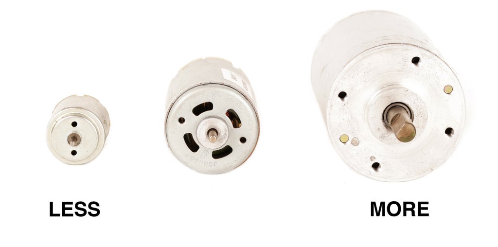
As a general rule, the larger of a motor you choose, the more voltage and current it can handle. This is important because there is a correlation between voltage and speed, and another between current and torque.

Put simply, the more voltage that is applied to a motor, the faster it spins.
However, like all electronics, motors have an optimal voltage range and should never exceed its maximum voltage. That means DC motors also have a maximum speed (at their maximum operating voltage).

For those unfamiliar, torque is the amount of rotational force a motor can apply. Like speed, motors also have a maximum amount of torque that they can produce before they stall (or stop spinning). As the motor encounters increasing resistance and gets closer and closer to stalling, the amount of current it draws increases. The absolute amount of current a motor can draw when it encounters so much resistance that it stops spinning is called its stall current.
The stall current is important because it will indicate a motor's potential power. The higher this number is, the more potential power the motor has. Although, when your robot's motor is spinning freely and not encountering much resistance, it will not draw nearly as much current.
Step 4:

Unlike the motor's voltage supply which can be varied by adjusting the voltage within its operating range, the options for adjusting torque are not so easy. You can simply get a bigger and beefier motor to solve this problem, or you can use a gearbox.

A gearbox is a collection of gears arranged in such a way that it translates the speed and torque of a motor to either increase or decrease (depending on the arrangement). The motor's shaft will be attached to one end of the gearbox, and as the motor spins, the rotation will get translated to a different speed at the output shaft of the gearbox.
As a rule, the faster the motor spins, the less torque it provides. Slower gearboxes provide more torque than faster ones, and vice versa.

It is rare that you would have to build your own gearbox. Many motors come assembled with a gearbox already attached in a host of different configurations. Geared motors are a great way to get a lot of power into a small package, or slow a DC motor down without relying on a motor controller to do all the work.
You can usually identify a geared motor because it looks like a normal motor, but with a bigger cylinder on the end. Also, the shaft is often off-centered.
Step 5:

By attaching the shaft of the motor to different mechanical systems, you can achieve different types of motion. These assemblies can ultimately be combined to create advanced electromechanical assemblies that solve different tasks. Albeit not quite robotic, the above tape player mechanism illustrates this.
Follows are the primary forms of motion you will achieve from a standard mechanism.

Rotary motion is the easiest to achieve because the shaft of the motor is already rotating. Typically, rotary systems involve increasing or decreasing the motor's speed of rotation. As mentioned, this also changes the torque of the system in relation. The type of rotary mechanism you will typically encounter involves gears or pulleys.

Linear motion translates rotational motion into motion across a flat plane. Classic examples of this include conveyor belts and tank tracks. This systems uses two or more rotary cogs or pulleys (one connected to the drive shaft, and one free spinning) to pull a flat track around them. The further the distance between these cogs, the longer the track will be. As the track gets pulled around the cogs, it moves in direction across a flat plane.

Reciprocating motion is a motion that moves back and forth in a linear fashion. This type of motion is often used to move a piston or in an automated door lock. There are many different ways to mechanically achieve reciprocating motion. Common approaches involve using a yoke (as pictured), a cam, or linkages.

Oscillating motion involves any part that moves back and forth along an arc. The most classic example of this motion is a metronome. Like most of the other movements, oscillating motion can be created by using a range of different mechanisms, including linkages. Most typically it just requires one part one a fixed pivot being pushed back and forth by some other part.
Step 6:
In order to achieve the different types of motion, you need to use mechanical parts. There are more mechanisms in this world than I could possibly go over, but here are some common ones you may encounter in robotics.

The simplest mechanism that you can attach is an off-centered weight on a rotary shaft. This will cause the motor to vibrate. These are most often used in vibrobots to create complex motion. This type of motion is the fastest path to get to gratification, but is also the most difficult to steer. The robot will tend to veer left or right, depending on which direction the motor is spinning, but it's movements will largely be arbitrary.

Pulleys are a type of rotational mechanism that can be used to change speed, torque, or - in some cases - motor direction. The nice thing about using pulleys is that they are friction based, so if the drive shaft they are attached to seizes up or gets stuck, the belts will slip and the motor will continue to spin. This puts less pressure on both the motor and electronic system from the motor having to work harder and draw more current as it gets closer to stalling. However, the bad thing about pulleys is that they can slip, so they are not as precise as other mechanisms. They are thus best suited for drive systems where motor precision isn't quite as important and the drive shaft is most likely to encounter resistance and stall.
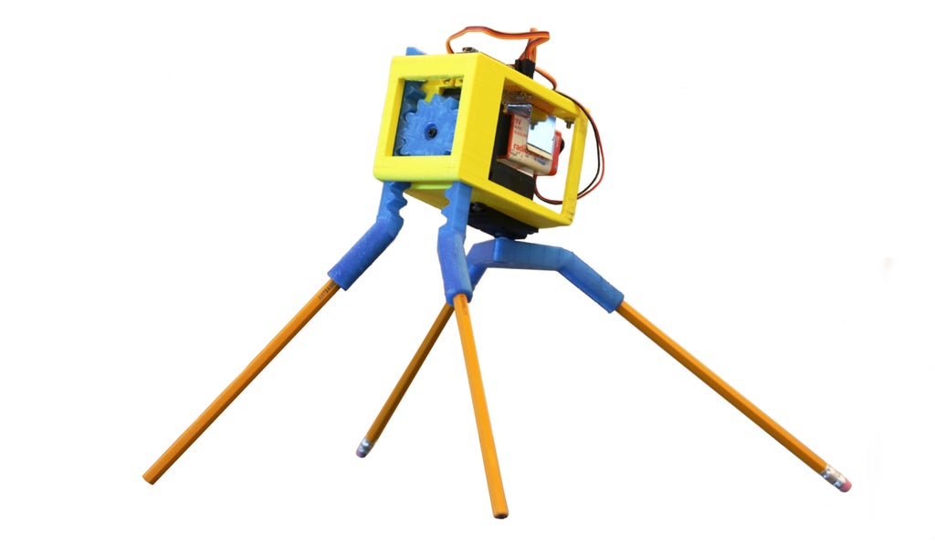
Another type of common rotational mechanism are gears. Gears function in many of the same way pulleys do. However, unlike pulleys, gears can also come in other shapes such as a "rack" configuration like in the 3D printed robot above, and be used to create linear motion. Gears also don't rely on friction to rotate the shafts, but rather have a series of interlocking meshed teeth. This makes them more precise since the meshing teeth ensure uniform and predictable amounts of rotation from one shaft to the next.
On account of the paired and meshing teeth, gears also require a very precise alignment. If they are too far apart, the gears will skip or wear down faster, and if they are too close together the gears will apply too much pressure and seize. Speaking of which, gear systems don't like to be stalled. This translates a lot of force to the teeth of the gear which are usually small and brittle. This can cause a tooth on the gear to break, which could lead to imprecision, or failure of the entire mechanical system. You can tell a geared system is broken because it is entirely seized up or is making horrible grinding noises.

A simple way to translate rotary motion to reciprocating, linear, or oscillating motion is to use a cam. A cam is just a lever arm which spins off-center from the shaft. The most common type of cam is oval shaped. However, cams can come in a number of different shapes and sizes, from rectangular shaped to heart shaped. Cams just push on things and can serve all kinds of purposes in mechanical systems. In this instance, the two cams are both lifting and propelling the robot forward as they are rotated by the servos.
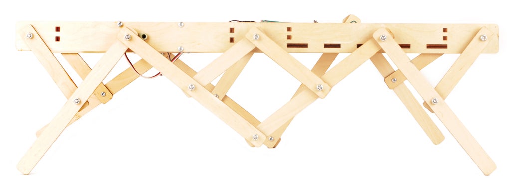
Linkages can be used to create reciprocating and oscillating motion. All that a linkage happens to be is simply a rigid bar with holes in it for pivots. In a linkage system, some of them are constrained to other linkages, and others are fixed to the surface upon which the motor is rotating. By creating a combination of free and fixed pivots, the linkages are able to create a multitude of complex motions.

Another common method to translate motion is to use tracks. Aside from making any robot look like a tank, this form of conversion creates linear motion. One of the benefits of a tracked vehicle is that its method of locomotion has much more surface area than a wheel. This enables it to have more friction with the ground, which is essential for climbing over uneven surfaces and obstacles. The fact that tracks inherently have a little bit of give across their length also doesn't hurt with this either since they are able to conform to slightly uneven planes.
Step 7:
Let's now take a moment to discuss some practical concerns.

To power a DC motor, all you need to do is connect a positive voltage (within its power rating) to one terminal on the motor, and ground to the other terminal.

To reverse the direction of the DC motor, simply reverse the wires connected to each terminal. The reason the motor spins backwards when you do this is that the magnetic poles created within the windings is reversed when you power it the opposite way. This forces the rotor to spin the opposite way to align with the fixed magnets inside the stator (motor enclosure).
We will go over controlling motors with a microcontroller (such as an Arduino) in the next lesson. However, as you can see from the project links below, there are many fun robot-like machines you can build with just this basic knowledge of motors.


![Tim's Mechanical Spider Leg [LU9685-20CU]](https://content.instructables.com/FFB/5R4I/LVKZ6G6R/FFB5R4ILVKZ6G6R.png?auto=webp&crop=1.2%3A1&frame=1&width=306)


