

Introduction: Inductors


Of all of the basic electronic components, inductors are probably both the simplest and most confusing to wrap your head around. Don't worry too much if all of this does not make too much sense. When just getting started with electronics, diving too deep into this is enough to induce a headache. Besides, they are not used quite as often as they used to be when building circuits.
Back in the old days when hobby electronics centered around radio, inductors were a big deal. Ever since everyone moved over to experimenting with microcontrollers and other solid state electronics, they have seemingly vanished. However, speakers, motors, electromagnets, reed relays, and transformers are all basically specialized inductors. While you may not often find yourself winding and tuning coils, inductors hardly went away, and it is still important to have a loose grasp on these concepts.
Step 1: Coils
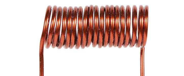
An inductor is basically a coil of wire. That's it.
It may be confusing to understand why a coil of wire would have any special properties at all.

Well, all wire creates a magnetic field when electricity flows through it. When the wire is coiled, it shapes the field and concentrates it towards its core, which increases its magnetic properties. The magnetic field that is created by the inductor holds energy, and when the current changes, the fields induces more current back into the circuit to try to keep it stable. Hence, the name inductor.

Whereas capacitors create electric fields and resist changes in voltage, inductors produce magnetic fields and resist changes in current.
On account of their ability to regulate current, inductors have many special uses in electronics. A majority of these uses are very complicated and related to their ability to affect AC electrical signals. Since we are going to largely be dealing with DC electricity, I will not be going over any of this in-depth. If you would like to read more about inductor theory and the math behind it, check out All About Circuits Vol. 2 (Alternating Current).

There is special type of wire typically used for making inductors called magnet wire. For all intents and purposes, it looks very similar to regular wire and is measured using the same gauge system. However, it does not have a rubber insulation like typical hookup wire.

Instead, magnet wire has a hard and extremely thin enamel coating that keeps it insulated without interfering with its inductive properties. In order to solder to this type of wire, you need to first scrape off the coating.

Different coils have different amounts of inductance. This is measured in Henries. Typically, most inductors are measured in the uH (microhenry) range.

You may see an inductor represented in a schematic as a series of squiggly loops or, if there is a core, as a bunch of squiggly loops cozying up to two parallel lines.
Step 2: Inductance of a Coil
Not all inductors are created equal. There are four key factors which affect the inductance of a coil.
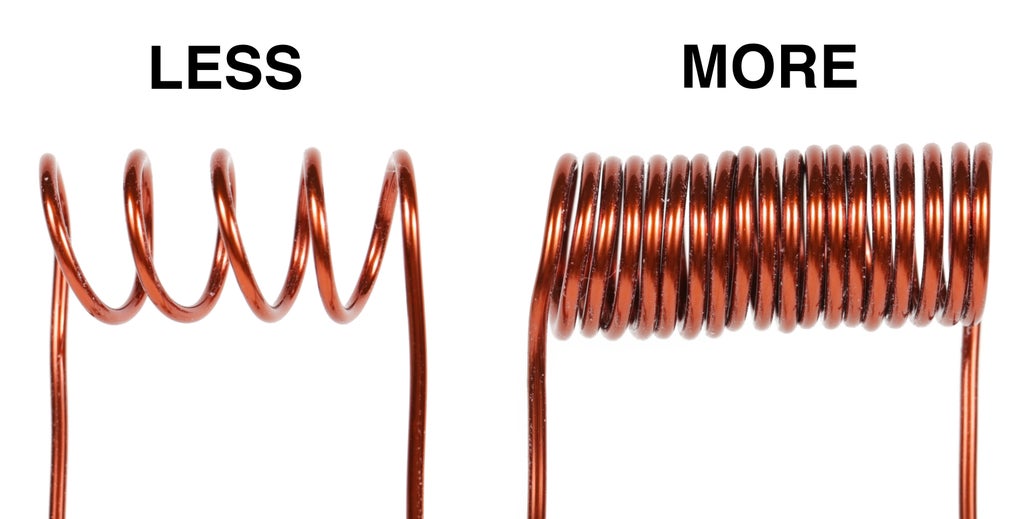
The first indication that determines the inductance of a coil is the number of turns (or loops) a coil has. As a general rule coils with more turns have more inductance than coils with less turns.

When dealing with inductors length also matters. Given two coils with the same number of turns, the shorter one has more inductance. The reason for this is that it's compactness helps it maintain a stronger magnetic field within it. As it stretches out, its ability to concentrate the field diminishes.

The diameter of the coil also determines the amount of inductance offered. The bigger the diameter, the greater the inductance.

Many inductors have a solid core at their center. By using a special core such as a ferrite rod (piece of iron), you can further increase the amount inductance.
Inductors without a solid core are considered to have an "air core." This offers considerably less inductance.
Step 3: Working With Inductors
Instead of diving deep into how inductors work, let's discuss common inductors you may encounter when starting with electronics, and what you might use them for.

Coils are typically what people are referring to when they talk about an inductor. As you already learned, it is just a coil of wire carefully tuned to maintain a magnetic field of a particular strength. These are ubiquitous within electronics, particularly when dealing with wireless devices. There are many different form factors you may encounter when dealing with coils, but they are all ultimately just coils of wire.
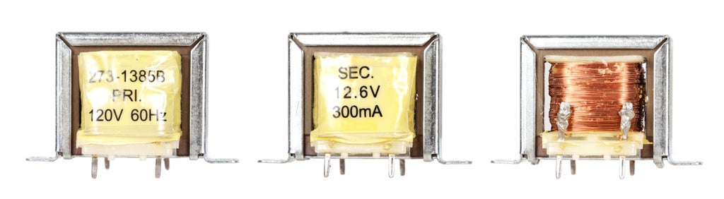
Transformers are two coils of wire that have been wound around a common core. The first winding is considered the primary (or input), and the other coil is the secondary (or output). When a current is sent through one coil, it induces an electrical field in the other coil. By changing the number of wire turns in each coil, each one has a different amount of inductance, and in turn - no pun intended - there is a different amount of voltage on the secondary coil than there is on the primary. The voltage present is in direct relationship to the difference ratio between the two coils. Put simply, if they have a difference of 10:1 primary to secondary, then there will be 10 times more voltage on the primary than the secondary.

Electromagnets are basically just coils of wire wrapped around a ferromagnetic core which becomes magnetized when electrically charged. Electromagnets are little different than single coil inductors. However, they are constructed in such a way that they are meant to function as an electromechanical device and not play a significant role in regulating electricity within a circuit.

You can experiment with making your own electromagnet very simply by wrapping a tight coil of magnet wire around a large nail. To power it up, scrape a little bit of coating off the ends of the magnet wire, and connect it to a 9V battery.

Reed relays are reed switches that have been packaged inside of a coil of wire. When a current is applied to the coil and it becomes magnetized, and the switch gets triggered. Relays are fantastic because the coil circuit is electrically isolated from the pins on the reed switch. In other words, you can use one circuit to control a switch in a completely different circuit without having to worry about them ever getting connected together. In this way, you can use a low voltage circuit to control an on/off reed switch in a much higher voltage circuit.

A solenoid is similar to an electromagnet in that it is just a coil of wire. However, it differs in that it has an unconstrained core. When energized, the core is either pushed or pulled linearly through the body of the solenoid. Often solenoids have mechanical components such as a return spring and/or lock ring to return them to their initial position and keep the core from getting entirely free from the coil.

An audio speaker too is actually just an inductor. If you look closely you will see a coil of wire sitting on top of a large magnet. When power is applied to the coil, it moves back and forth, which vibrates a thin diaphragm called the cone. The cone then displaces air and creates sound waves in relation to the its movement.
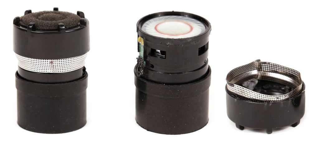
And if that were not enough, dynamic microphones are basically inductors too. They are constructed very similarly to speakers, except they work in an opposite manner. When the fluctuating air pressure created by a sound wave hits a thin diaphragm, it moves it back and forth, which in turn creates a proportional voltage to the sound. This voltage is typically fairly small and needs to be amplified.

Last, but definitely not least, we have motors. While a bit too complex to be considered a true inductor, just like everything else listed here, they contain coils and operate based on principles of inductance. To over-simplify the matter, when power is applied to a DC motor, an electrical field is created which spins the motor in one direction. When the polarity to the motor is reversed, the magnetic field is flipped and it spins the motor in the opposite direction.
Step 4: Transducers
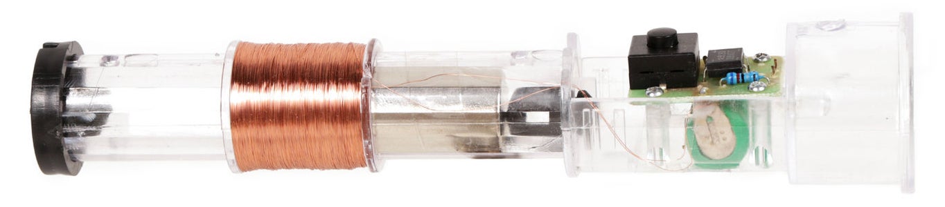
Another interesting (and very important) thing to note about inductors is that they are also transducers. A transducer is anything that both can be actuated with electricity to create a physical force or, alternately, create electricity when a physical force is applied upon it.
Look at the inside of this shake flashlight. Notice that there is a coil with a loose magnet inside. When the magnet passes back and forth through the inside of the coil, it induces an electrical current, which is then stored by the circuitry inside the flashlight. In a way, this is a little bit like a backwards-operating solenoid, and is by no means unique to this component.
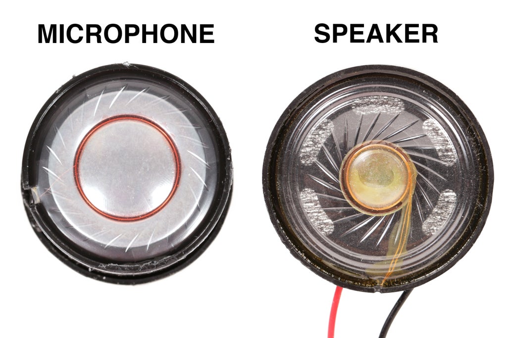
This may take a moment to wrap your head around, but a passive microphone is just a speaker being used in reverse. Both components have nearly identical parts. The only difference is the inductance of the coil and the arrangement of the magnet have been fine tuned for their particular tasks.
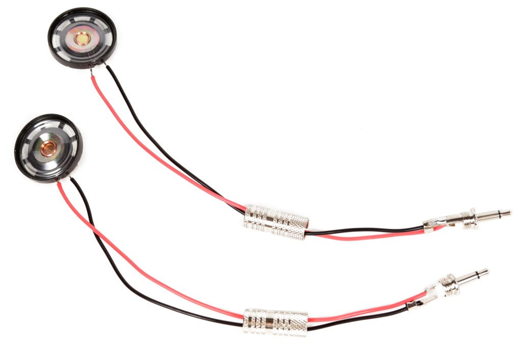
If you still don't believe me, try this experiment. Solder two identical small speakers to 1/8" mono plugs.

Insert one speaker into the input of the test amp and the other into the output. Talk into the speaker connected into the input and notice how the sound is being amplified from the output.
The speaker you are talking into is creating a voltage in the coil when sound waves vibrate its diaphragm. The output speaker, in turn, is vibrating it's diaphragm and creating sound waves when an amplified voltage runs through its coil.


