

Introduction: Multi-Source Controlled USB Lamp


If you don't mind having a bit of fun with electronics this project is for you.In this instructables I am making a ATtiny based tiny USB lamp that can be turned off/on by multiple sources such as
- Knocking
- Clapping
- Blowing
- Finger Snapping
- Shouting
In this Project I utilized or I can say ,I misused microphone sound sensor to detect different sources to turn on and turn off lamp.Also I wanted to make this project as small as possible ,so I used a ATtiny 85 microconntroller.This is cool because the ATtiny is tiny, and - well - this allows you to make tiny things that don't need a big microcontroller.
Basic Idea:
A microphone is an acoustic to an electric transducer or sensor that detects sound signals and converts them into an electrical signal.
To generate an electrical signal all you need to do is make movements in the diaphragm. So when blowing on a microphone sound sensor, microphone’s diaphragm responds because it is a displacement of air molecules pushing on one side of the membrane to the other causing electrical signal in the microphone to make it seem like sound.
--------------------------------------------------------------------------------------------------------------------------------------
Also This instructables describes how to program ATtiny microcontrollers using the Arduino IDE.
Lets get Started.......
Step 1: Watch the Video
The video goes through the build process as well,if you prefer to learn that way!
Step 2: Get the Parts and Materials!


You will need following parts to flash ATtiny through Arduino:
- Arduino
-Breadboard
-ATtiny85 (or ATtiny45)
-10uF electrolytic capacitor
-Jumper Wires
You will need following parts to build the final circuit:
- ATtiny85
- Microphone Sound Sensor
- LED
- 220 ohm resistor
- IC socket
- Perfboard
- USB Cable
Note:
The value of resistor in series with LED may be a different value than 220 ohm ,the LED will lit up also with values up to 1k ohm.
Other Tools and Materials:
- Glue Gun
-Utility Knife
-Bottle Cap
-A white paper
Step 3: Wire the Circuit to Flash ATtiny


Connect the Arduino to the ATtiny as follows:
- Arduino +5V ---> ATtiny Pin 8
- Arduino Ground ---> ATtiny Pin 4
- Arduino Pin 10 ---> ATtiny Pin 1
- Arduino Pin 11 ---> ATtiny Pin 5
- Arduino Pin 12 ---> ATtiny Pin 6
- Arduino Pin 13 ---> ATtiny Pin 7
Put the 10uF capacitor between ground and the Arduino reset pin. Make sure to keep an eye on the capacitors polarity (ground to ground!).
This capacitor effectively filters out the incoming reset pulses that come from your PC when the Arduino software starts to program your part. Because you want to program a part further downstream, you filter the reset pulses coming into the Arduino. Otherwise, you’d invoke the Arduino’s bootloader and program that Arduino, and that’s not what you want at all;);
Step 4: Set-up Arduino IDE

- Connect your Arduino, open the IDE, and upload Example> ArduinoISP sketch;
This Arduino-supplied example sketch turns your Arduino into an ISP (in-system programming)
Again ;
- Open Arduino IDE
- File > Preferences and in Additional Board Manager URLs: and Copy/Paste this:
- Click OK
- Tools > Board > Manager, install: ATTiny and close Arduino IDE.
Configure Arduino IDE Tools menu like this:
Open Arduino IDE,
(1)Board: ATtiny25/45/85
(2)Processor: ATtiny85
(3)Clock: Internal 1 MHz
(4)Port: COMXX(Arduino Uno)
(5)Programmer: Arduino as ISP
Upload the below given code:
int led =0;<br>int sensor=1;
int state1=HIGH;
boolean value=0;
int state2=LOW;</p><p>void setup()
{
  pinMode(led,OUTPUT);
  pinMode(sensor,INPUT);
}
void loop()
{
value=digitalRead(sensor);
if(value==HIGH && state2==LOW)
{
  if(state1==HIGH)
    state1=LOW;
  else
    state1=HIGH;
}
digitalWrite(0,state1);
state2=value;
}
Also you can get Code and circuit diagram from my Github page .
Step 5: The Prototype!


THE FIRST RULE OF ENGINEERING IS YOU NEVER BUILD ANYTHING WITH REAL MATERIAL UNTIL YOU BUILD A PROOF OF CONCEPT MODEL
So I build a prototype on a breadboard to test the circuit.Follow the circuit circuit diagram to complete the breadboard connection.
And it works Fine:)
Note:
If the led is not lighting up, you need change the sensor sensitivity (reduce Sensitivity) by rotating the potentiometer .
Step 6: Breadboard to Perfboard
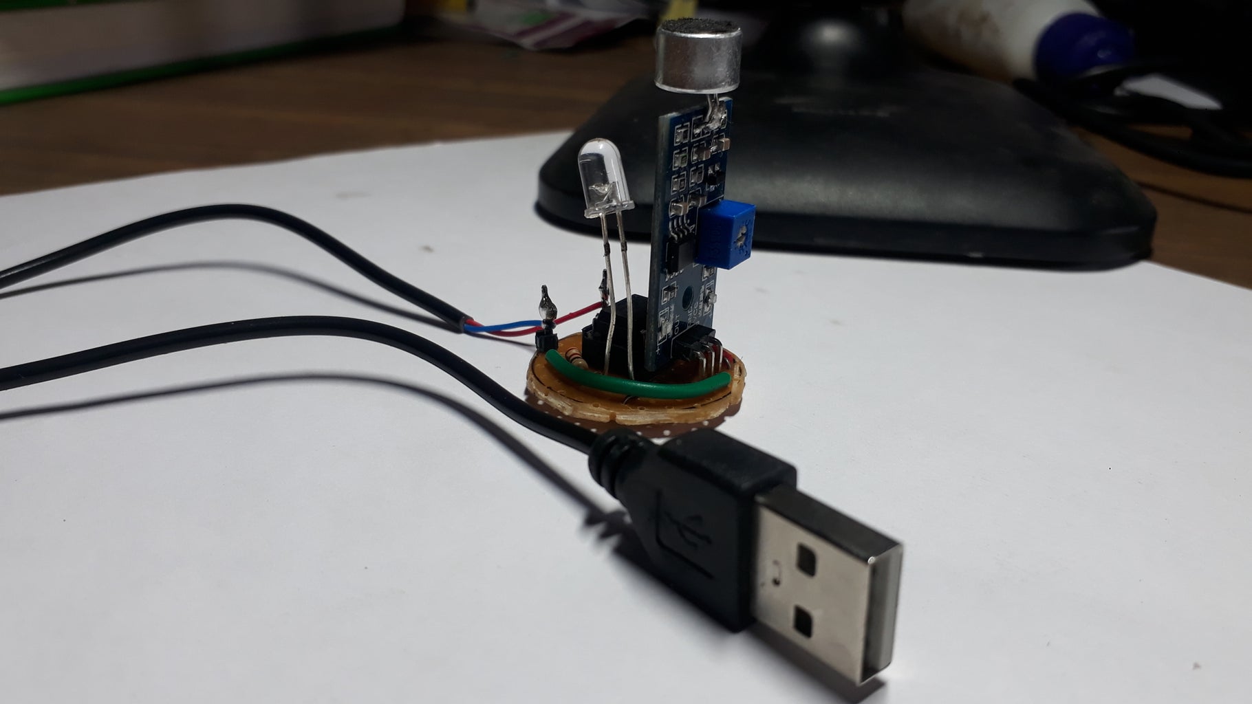


I cut perfboard into a size of coin and I soldered all parts into it.I soldered a usb cable , so I can power it from any USB Ports such as laptop,power bank etc.
Step 7: Next ?


I decided to build a base and lamp shade .For that I used a bottle cap and a piece of white paper.
- By using a utility knife cut out some portion from bottle cap to insert usb's wire.
- Fix the circuit into bottle cap using hot glue gun.
- Get a white paper and join it using hot glue.It must look like a hollow cylinder.
- Insert the paper through top of circuit and fix it with Glue.
Thank youso much for reading if you need any more information feel free to ask in comments,and I'll do my best answer you.

Participated in the
Audio Contest 2018


