

Introduction: Wearable LED Matrix Display Badge


Are you running an event ,competition or even hosting a birthday party ?
Badges are versatile item that can make introductions and celebrations that much easier .You would never begin a conversation with "hello , my name is ............." so why should your badge?
So lets design a PCB Badge that you can pin proudly and wear at your next important event.
In this project, I will be showing how I built a badge-sized ATtiny85-based LED matrix display (5x4 matrix). I have used Charliplexing technique for driving 20 LEDs using ATtiny85.
you can even easily add extra texts to your badge as you wish.Standout from the crowd with this awesome PCB badge.
Lets get started :)
Step 1: Watch the Video
The video goes through the build process as well, if you prefer to learn that way!
Step 2: Things Used in This Project


Hardware components
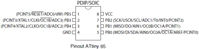
- Microchip ATtiny85 x1
- Coin Cell Battery CR2032 x1
- 3 mm LED x20
- CR2032 Coin Cell Holder x1
8 pin DIP IC Socket x1
Slide Switch x1
Resistor 100 ohm x5
To program ATtiny85 you need an arduino uno or any other arduino boards.
Software apps:
- Arduino IDE
Hand tools:
- Soldering iron
Step 3: Charlieplexing
Charliplexing is a technique for driving a multiplexed display in which relatively few I/O pins on a microcontroller are used, e.g. to drive an array of LEDS. The method uses the tri-state logic capabilities of microcontroller in order to gain efficiency over traditional multiplexing.
The formula for Charlieplexing isLEDs = n^2 - n
where 'n' is the number of pins used.
I use an ATtiny85 programmed with the arduino as ISP.So it uses 5 pins for 20 LEDs.
More info on Charlieplexing: http://en.wikipedia.org/wiki/Charlieplexing
Step 4: Schematic Diagram

Step 5: The Prototype!


Before designing a PCB, I decided to build a prototype on a perfboard.
And it worked fine......
Step 6: PCB Design


I used KiCad for PCB Design.The edge cut were made using .DXF file which was designed and generated using Autodesk Fusion 360.
The size of PCB badge was 55*86 mm.
I quoted and ordered PCB through PCBWay.com.
Note:
The White Silk Screen On the center is provided to Write your Name or Whatever you want :)
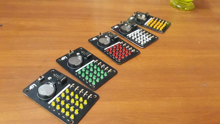
After soldering the PCB looks like this:
This project is open source. If you would like to build your own, all of the resources are available in the my GitHub page.
Step 7: Wire the Circuit to Flash ATtiny
(DON'T insert the battery now.)
On the PCB I have provided 6 pin connector for programming ATtiny85.the small dot near the 6-pin connector is the first pin (MISO), see the photos for alternative connections.

- Arduino +5V ---> VCC
- Arduino GND --->GND
- Arduino pin 10 --->RST
- Arduino pin 11 --->MOSI
- Arduino pin 12 --->MISO
- Arduino pin 13 --->SCK
Follow the below link for programming ATtiny:
The Instructables Community Manager randofo had written a nice instructables on "Program an ATtiny With Arduino".
you can download all source files from my githhub page:https://github.com/amalmathewtech/ATtiny_LED_Matrix_Display_Badge
After Configuring Arduino IDE Tools Menu, upload given arduino sketch
Note: update 11th line of arduino sketch to display as your wish
Attachments

Step 8: Sneak Peek Video
Have fun :)
Thank you so much for reading if you need any more information feel free to ask in comments, and I'll do my best answer you.
If you like this project you can support my project by Voting it for Party Challenge .
You can also support my project on PCBWAY's I can Solder KIT 2019 contest
/>
Happy making! :)

Participated in the
Party Challenge


