

Introduction: Parallel Finishing


Now that you've roughed the spoon and machined the hole in the handle, it's time for finishing. Parallel Finishing is a good all-purpose strategy for machining complex surfaces with high accuracy.
1) In the ribbon, choose 3D>Parallel.
The popup defines Parallel:
"A widely used finishing strategy, the passes are parallel in the XY plane and follow the surface in the Z-direction. You can choose the angle as well as the stepover in the horizontal direction...Parallel finishing passes are best suited for shallow areas and can be confined to machine only up to a given contact angle."

2) Click Select next to Tool, and choose 1/2" Ball (1/2" Ball EM Short). Click OK.
Always use ball nose endmills for 3D finishing, because the radius on the end of the tool will give you a smooth, precise finish. The larger the diameter of the ball nose, the better the surface finish, because the cusps (scallops) between each pass are more shallow and therefore more difficult to visually detect. The only reason to choose a smaller diameter ball nose is to reach tighter crevices or smaller details.
3) Click on the Geometry tab.

4) Note that by default, the geometry of this toolpath will follow the silhouette of the model. You don't want to finish the stock that the spoon tabs are attached to. In the dropdown next to Machining Boundary, choose Selection.
5) Look at the model from the side. Carefully select the contour that runs along the side of the spoon, as shown in the attached screenshot. The toolpath boundary will appear as a green contour.
If you make a mistake and select the wrong contour, press click X next to Chain by the Machining Boundary Selection and start again.

6) Next to Tool Containment, select Tool Outside Boundary. This will ensure that the tool machines along the sides of the model--not just its top surface.
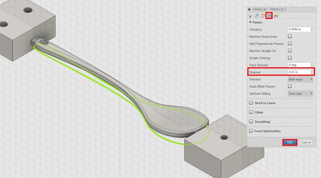
7) Click on the Passes tab.
8) Change Stepover to 0.03.
The smaller this number, the finer the surface finish.
9) Click OK to generate the toolpath.
Step 1: Parallel Toolpath Editing

If you view this toolpath from the side, you can already see the bottom height is unnecessarily low. You only need this toolpath to go to the bottom of the edge of the model.
1) Right click Parallel 1, and choose Edit.

2) In the Heights tab, under Bottom Height, change the Offset to 0.3.
3) Click OK to generate toolpath.
Step 2: Simulation Crash!
1) Click Setup 1.
2) In the ribbon, click Simulate.
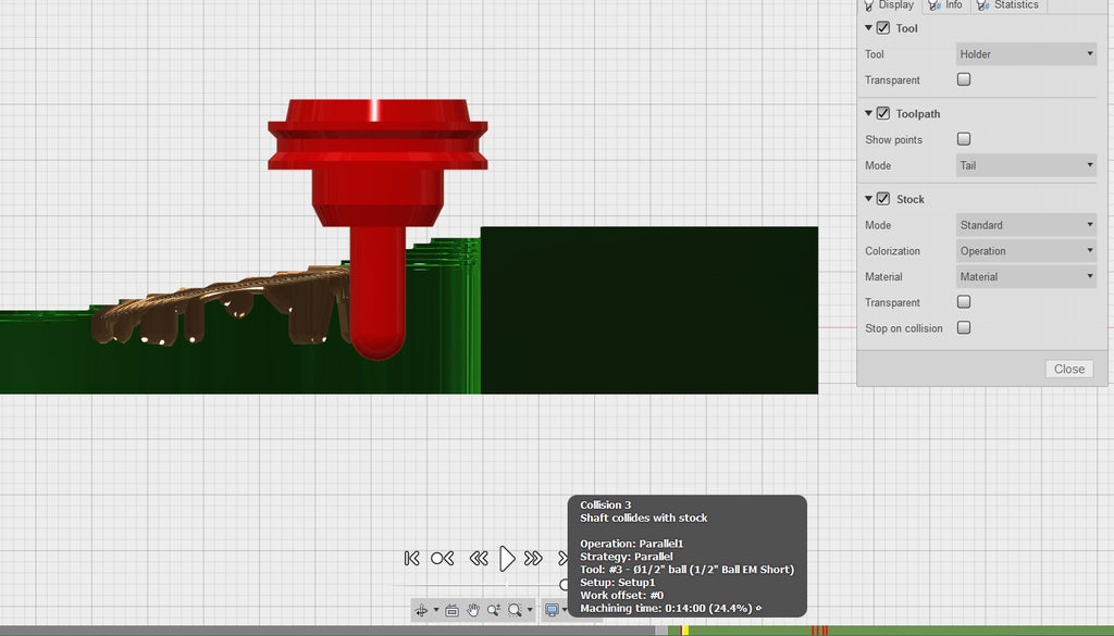
Something is going wrong! When the tool turns red and red dashes appear in the timeline, this indicates a Simulation Crash. You will need to constrain your toolpath in some way to remove the simulation crash before post processing. If you hover your mouse over one of the red dashes in the timeline, you'll see that the collision is labeled "Shaft collides with stock."
There are three types of simulation crashes:
-Shaft collides with stock: The tool is trying to cut beyond the length of its cutting flutes. Increase your bottom height or choose a longer tool.
-Holder collides with stock: The holder of the tool is hitting stock. Change your heights or machining boundaries.
-Rapid collision with stock: The tool is trying to move through stock at rapid speed. Check your lead-in and lead-out parameters.
Use the view cube to view the spoon from the side during a collision. You can see that this tool is too short to handle cuts of this depth. You will need to choose a longer tool in your next edit, but for now, analyze what's here.

4) Looking at the simulation controls, click the "Go to End of Toolpath" button, three over from the Play button. You'll notice that the model is interfering with the view of the stock. In the CAM Feature Tree, click the light bulb next to "DMS_spoon_certification_part." It will turn off the visibility of the model.

5) You'll notice that the top of the spoon looks nice and smooth, but the sides of the spoon are pretty rough. You'll need another finishing strategy to tackle the sides of the spoon, because Parallel doesn't produce a good finish for steep walls.
Step 3: More on Simulation Crashes
Let's pause for a moment to go into greater detail about simulation crashes, so that you understand how they work before moving on.


-Accurate collision detection depends on Fusion knowing information about your tool. The tools in the DMS library have their flute length, body length, and holder modeled for you, to give you very accurate collision data. This is not the case for any custom tool, such as drills, and you will need to manually measure your tool against the heights in your toolpath. You can always edit the geometry of custom tools and holders to ensure accurate collision detection, but this is not covered in this class.
-CAM simulation will not tell you if you're being too aggressive. For example, you could have an optimal load set to 100% of your tool diameter, and the simulation will not show any issues. However, you know that the optimal load should not be greater than 50% of the tool diameter without damaging the tool or ripping up the stock.
-CAM software does not include collisions with fixtures by default. If you're planning to use clamps on the corners of your stock, for instance, you'll need to keep this in mind when toolpathing, or even better, model the clamps yourself and choose them as Fixtures in your Setup.
Step 4: Switching Tool and Editing Tool Number
Back to the spoon. Turn its visibility back on in the CAM Feature Tree.
1) Right clickParallel1 and choose Edit.
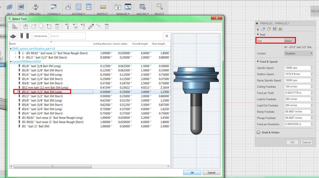
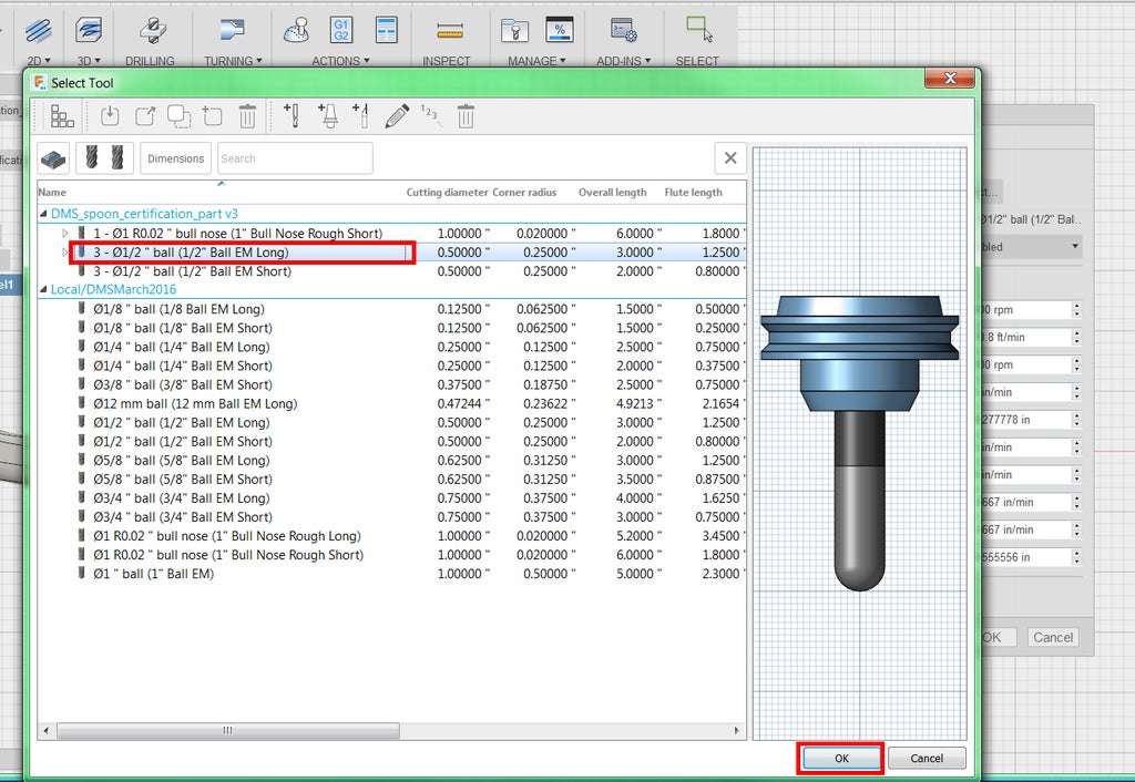
2) Choose Select next to Tool, and choose 1/2" Ball (1/2" Ball EM Long). Click OK.

3) While still in the Tool tab, notice that the tool is labeled #4.
On the left side of the screen, in the browser tree, notice that the tools for Adaptive1 and 2DPocket1 are labeled T1 and T2, respectively. The CAM software automatically adds another number to the tool number each time you select a new tool.

When doing CAM for the DMS, you want to ensure that your tools are numbered in chronological order. When you post process your program, this tool number will be the label for that tool in the G-code. When you insert tools into the machine, you will assign them the same number. The DMS will keep track of each tool by number, and when it's not using a tool, it will store it in its numbered slot in the magazine behind the machine.
To keep yourself organized, you want to make sure your tools don't skip numbers or go in non-sequential order in the CAM software. It would be easy to accidentally label a tool #3 if it's the third tool you insert into the DMS, but if the G-code refers to it as T4 (tool 4), the DMS will either give an error message or choose the wrong tool.
In other words, you need to change your tool number to #3.
4) Click Select next to Tool again.

5) Right click Tool #4, 1/2" Ball EM Long, at the top of the window under DMS_spoon_certification_part, and choose Edit.
Don't edit the tools in the DMS tool library.

6) In the window, click the Post Processor tab.
7) Change Number to 3. The Length and Diameter offset should automatically switch to 3 as well.
8) Click OK.
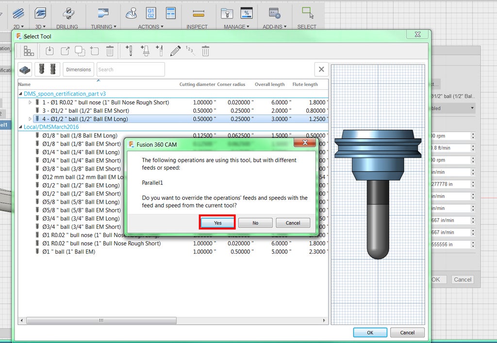
9) The CAM will give you a pop-up window every time you change a tool number, but it's fine to do this override. Click Yes.
10) Now you'll see the 1/2" Ball EM Long under DMS_spoon_certification_part, but it's now labeled #3. Select it and click OK.

11) Confirm in the Tool tab that the tool is now #3. Don't generate the toolpath yet.
Now you know how to edit tool numbers. For your own DMS CAM programs, it is a good practice to wait until you're done with CAM and have simulated multiple times before editing the numbers. This will save you some time because you never know when you're going to change a tool, rearrange the order of toolpaths, etc.
Step 5: Parallel Toolpath Editing Continued
You'll want to make a few more changes before generating the toolpath.

1) Click the Passes tab.
2) Check the box next to Stock to Leave.
3) Change Radial Stock to Leaveto 0.01. Make sure Axial Stock to Leave is still 0.
Axial Stock to Leave is the amount to leave along the Z axis--that is, on the top or bottom of the part.
Radial Stock to Leave is the amount to leave on the X and Y axes--that is, on the walls of the part. By default, the radial stock to leave follows the set axial stock to leave.
By leaving some radial stock behind, you just ensured that the tool leaves some material on the sides of the spoon model. You'll be finishing those with another toolpath that is better for steep walls. If you didn't leave stock behind, the finishing toolpath might not smooth out the rough edges caused by this Parallel toolpath.
In the future, if you ever need to machine into your model, you can set Stock to Leave to negative numbers.
4) Click OK to generate the toolpath.
5) Click Setup 1.
6) In the ribbon, click Simulate.


7) Turn off the visibility of the solid model so it doesn't interfere with the stock, and inspect.
There are no more collisions, the top of the spoon looks good, and you've correctly prepared the stock for finishing the steep walls.


