

Introduction: Ammo Box Power, Light, and Sound Kit


PROJECT UPDATE 9/12/16:
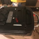
Well, my wife took it to the beach this Summer, and the steel plate panel rusted. While I was replacing the panel, I made some other updates to it. In particular:
- I replaced the steel panel with a poly cutting-board.
- I added a bus for the negative power to match the positive.
- I replaced the stand-alone USB and 12V jacks with an integrated USB / 12V / voltmeter.
- I took the puny inverter off and added a connector for a 1500W inverter. Now I can run my microwave, fridge, and coffee maker.
- I changed the switches.
- I added a light to back-light the new panel.
- I added a 12v socket with a dimmer. Without the dimmer, my lights were too bright for some applications.
- I removed the fan. Didn't need it, and it took up too much room.
Please see step 13 for detail on the updates. I apologize that I don't have time to update all of the steps to reflect updates.
Good luck with your own projects!
Judd
I call this project "Tactical Power Projection." The basic idea: a go-anywhere Swiss Army Knife of power, music, and lights. I can take this box to a campout, hunting lease, beach, night fishing, etc. and keep the lights on, keep the phones charged, and keep the tunes blasting all night. It's durable, water-proof, portable, and (I think) pretty cool looking.
I was very impressed with the Portable Sun Rechargeable Work Lamp and thought it would be cool to make one. About the time I started researching it, my 25-year-old boom box in the garage crapped out, so I started looking at 'build-your-own-speaker-systems' like this and this.
The idea came together to create a component system combining:
- A power supply
- An amplifier and speakers
- Spotlight and area lights
- Maybe a HAM radio (not installed yet)
I'm pretty happy with where the project is right now. I have a flexible portable power supply that can do anything I need to do for camping or for a temporary power outage. I also have a pretty damned loud stereo amplifier, with bluetooth and 3.5mm input. Finally, I can run lights all night. Plenty bright to work or to light up washer pits.
It will run 8 hours with lights and music, or over 30 hours with just music.
I still have things I want to do with it (rework the panel, add a HAM radio, 5.1 surround?, pico projector?..), but I'm also very happy with what it is now.
I've had a lot of people ask me how to make it, if I'd make them one, how much would it cost, etc. I also wanted to give back to Instructables because they helped me get this and other projects done. Finally, I'd love to win a contest! I need a Dremel!
You can build this. If you like it, you should give it a shot. I've tried to be very thorough and specific in the directions so you can duplicate my success.
*** If you like this project, please consider voting for me for the First Time Author contest and the Survival contest! I need a Dremel! And another Leatherman!
Step 1: Enter, Stranger, at Your Risk. Here There by Dragons.
WARNING NUMBER 1: I don't know anything about electronics and am not qualified to give you advice. This project is full of things that can hurt you, kill you, burn your house down, explode, electrocute, etc. There are several ways to die or seriously hurt yourself in this project. If you don't know what you're doing, then you need help beyond this instructable. IF YOU FOLLOW MY INSTRUCTIONS AND DON'T LEARN TO WORK SAFELY FIRST THEN YOU ARE A DANGEROUS FOOL. Educate yourself. Follow these safety tips, but don't expect that they will keep you safe. They are a starting point.
SAFETY TIPS:
- Make sure you don't cross the terminals on the battery, either directly or through a circuit. Keep the terminals covered.
- Keep ventilation open, even with a Sealed Lead Acid battery. In theory, these batteries don't leak. In reality, everything fails. You don't want to have hydrogen gas explode in your face.
- Use fuses for every circuit, and use the adequate fuse type and rating for your load.
- Go slow. Hook up one circuit at a time and double-check it before you flip the switch.
- Draw a circuit diagram.
- Use big wire if you're going to use an inverter with this project. Read the documentation that comes with the inverter, or do some research.
- Make good connections. I crimped terminals for the most part. I have one wire nut in the project, and it's taped down for security.
- Use shrink wrap on your connections. Minimize bare metal and sparks.
- Use shielded connectors. Minimize bare metal and sparks.
- Use a charger that's made for the battery you're using. A safe project will melt down and cause a fire if you use the wrong charger.
- Don't puncture your battery. You're going to mount it to a board, and it's going to be tempting to put a screw into the battery. Very bad idea.
(Since I don't know what I'm doing, I would welcome additional safety tips to include here...)In review: You could die or burn your house down. I don't know what I'm doing. If you're going to recreate this project, then YOU NEED TO LEARN how to do so safely. Don't guess if it's going to work safely. Research and assure yourself before you plug it in.
WARNING NUMBER 2: This is not a cheap project. Almost all of the parts I bought specifically for this project. You can scrounge parts and probably do this for 100 bucks or less (old Peg Perego battery, old car stereo, ...). That's not what I did. Don't go into this thinking it's going to be cheap. OK, now that I've run half of you off, GO FOR IT! Build something you're proud of.
Step 2: Tools and Equipment
There are better ways to do this. Given the materials budget (or lack thereof - see step 3) I couldn't spend a lot of money on tools. Here's what I used:
- Hacksaw
- Hacksaw blades for use on steel.
- Electric Jigsaw. Get one with some power. I burned an old one up, and I wish I had bought the new one when I started the project. It was night and day. Black and Decker JS660.
- Jigsaw blades for use on steel.
- Drill
- Drill bits. I bought a 14-piece Dewalt Titanium Pilotpoint set for about 15 bucks at Home Depot.
- Assorted zip ties.
- Clamps. I used some big woodworking clamps, some c-clamps, and pinchers to keep stuff pinned down while cutting, drilling, grinding, etc.
- Various flat and phillips screwdrivers
- Various metal files. Get a 4-pack of files. Beveled and flat big, triangle and cylinder small.
- Wire tool. I used the cheapie $10, red-handle jobbies and I got by. When I build the next one, I'll probably invest in a better tool for crimping connectors.
- Needle nose pliers
- Regular pliers
- Tin Snips (for cutting zip ties, etc).
- Cigarette lighter (for shrink-wrap)
- Safety goggles (ESPECIALLY when grinding and cutting metal)
- Grinder
- Ear plugs (for grinding and cutting metal)
- Gloves
I don't have a Dremel, but it would have really been useful. Maybe for my next project... :D
Step 3: Materials
Philosophy that Drove my Purchasing Decisions
My goals for this project:
- I wanted to build something I was proud of.
- I wanted it to work pretty much without any TLC. I unplug the battery, throw it in the truck, take it out, turn it on and it works every time. I don't want to waste time troubleshooting in the field. I bought some POS bluetooth dongle for a different project and it taught me a lesson: spend more for gear that works.
- I want my boys (one of them, anyway) to use it when they're my age. They'll probably need to change the battery by then, but you know what I mean. It needs to hold up. A cooler speaker system wouldn't last that long. There isn't a whole lot of plastic in this project.
- Pretty loud, but not too loud. I don't do raves. But I like heavy metal (among others). Usually, we're running it at about 50% volume.
- Portable. I wanted to be able to carry the whole thing in one trip.
- Power for days. I had three scenarios I planned for (this drives battery and inverter selection):
- Music and Phone Charging for 3 days. Done. We don't run it the entire weekend, but I've exceeded 30 hours of typical listening without recharging.
- Emergency Power for 7 days. (small lights, phone charging, little things). Haven't done it yet, but I'm confident.
- Remote Power for as long as possible. For example, run job-site tool chargers, lights, etc. Or, run lights for a washer pitching tournament. I'm good for lights for over 8 hours.
As a result of these goals, I researched and selected the following products:
Surplus Store - $55.
(Sorry, not telling you where I get these. If you look, you’ll find them.)
- 1X M548 Ammo Can – 14” X 17 ¼”. I would not recommend the PA-120. You might be able to fit everything in, but I doubt it. 35.00 (YMMV)
- 2X .50 Cal Ammo Can. 20.00 (10.00e). (YMMV)
Amazon - $319.
- 2X Cabinet Handles (to lift chassis out of housing) - 1.33 each. (2.66 total)
- Insulated Quick Disconnect Terminals - 16.99. Insulated is a safety feature.
- Heat Shrink Tubes - 8.99. Another safety feature. You might look for a set with more of the bigger tubes. I ran out and had to scrounge.
- Battery Cables - 7.34. Safety is everyone's responsibility.
- Blue Sea Systems 10 Gang Bus - 16.22. More safety. Don't skip this. You might get another one for the negative terminals too - I probably will.
- Blue Sea Systems Dual USB Charger Socket. 9.88. Be careful with the seller - get the one sold by Amazon. Another seller (also ON Amazon) sent me a socket with a cheap USB plug-in. You want the 1-piece, integrated dual USB sockets as PART of the 12V housing.
- Schumacher SC-300A Speedcharge 3 Amp Charger / Maintainer - 25.53.
- Pyle PLMRMBT5S Marine Grade 600 Watt Amp Bluetooth 2-Channel Amp - 73.69 (looks like they went up a little bit.) Lots of reviewers don't like this product very much, but it's perfect for this project. The complaints in the Amazon reviews are irrelevant to me. They don't think it's 600 Amps. I don't care because it goes louder than I'd ever use it (just barely). Quality is good, easy to install, and it comes pre-wired, with connectors, etc. I bought another one, and I'll probably buy more. This saved me from having to buy a cheap audio head unit for the bluetooth.
- Pioneer 6X9's - 42.97.
- Plumbers Tape - 4.99. Safely secure the battery to the chassis.
- Chrome Battery 35AH 12V DC Deepcycle SLA Battery - 74.90. Love it. I looked at several different options. This was the right balance on weight / capacity / price / size.
- Lights - 19.00. These are awesome. I might get more.
- DC Extension Cables - 16.00. For the lights.
Home Depot - $40.
- 4 small shelf l-brackets. (Mine were steel, and about .50 cents each. This just shows you what they look like.)
- 4 threaded metal rods. 1/4". 8.00 total.
- 8 1/4" bolts. Couple of bucks. Get ones that fit the metal rods. If you're going to try wing nuts, plan for the handles. I didn't. :-)
- A metal sheet - 19.97.
- 4X rubber washers - 1.00. If you're going to use metal for your panel, get 1/4" flat rubber washers for the stereo jacks. They're probably about a dollar for a packet of them.
- PVC. About 10 bucks worth. I used 1/2" and 3/4" for the light stands. You'll need connectors and end caps.
OK, a word about the interface panel. I built the prototype with thin wood, which you can see in the pictures. It was temporary, and it was flimsy once it had everything attached to it. I would recommend that you also prototype in wood, especially, to test / practice your cuts, dry run, etc.
I really like the metal look, and I'm thinking about keeping it. However, if I were to build it today, I would probably not use metal for the following reasons:
- It drove A LOT of extra time. Especially with the tools I have. If I do it with metal again, I'll have access to a laser cutter. With the tools listed in Step 1, it was time consuming to make big holes for the DC jacks, the 3.5MM jack, the inverter, and the amp controller. I would cut with the jigsaw, bend, grind, and file. Test it, cut it with snips, grind, and file some more.
- You have to insulate everything electronic that comes in contact with it. ESPECIALLY the speaker jacks. I have rubber washers insulating them now, which is an OK solution, but rubber is not durable. I also need to put some sort of rubber gasket on the inverter, or I'm going to get worried.
- It rusts.
I expect that I will do one of the following eventually:
- Keep the metal, but add a small wood panel for the speaker jacks. When I do that, I'll sand the rust off and paint it Olive Drab.
- Replace the metal with poly. I'm thinking a cutting board.
- Replace the metal with wood, stain it, make it look nice. This may be accompanied by a change to metal switches instead of the current plastic ones.
Radio Shack - $151.
I went to 2 local stores as they were closing. I got A TON of stuff for 50-70% off. I probably paid $50 for all of this, but knowing that doesn't do you any good. These prices are what I could find for the similar or same parts.
- Inverter - 30.00. This is the one I got, no longer available at RS. I'll upgrade this to 1000W+ and one I can disassemble and flush-mount the jacks. Get big cables (like battery cables) if you're going to get close to rated wattage.
- 12V DC Jack (Female) - 8.00. Comes with a fuse holder.
- 3X Switches - 12.00 (4.00 e). I used SPST, so you should too if you're going to follow my wiring diagrams. Other than that, get ones you like.
- Binding Posts - 3.50. Make sure you get the bigger ones. The small ones are small.
- 4X Speaker Jacks - 14.00 (3.50 e)
- 12V PC Fan - 20.00. If I'm running the amp and a load on the inverter, I don't want anything locking up. So I got a big fan. This may be too big in terms of the space it takes in the panel. When I reconfigure the panel, I'm thinking about making the fan removable so I can use it to keep myself cool if I want to. Or swapping it for a smaller fan.
- 2X Mono speaker cables - 21.00 (10.49e) Seems like mine were a lot cheaper than this, but I can't find them online.
- 5X Fuse holders - 17.50 (3.50 e). Get a couple of extra so you won't be tempted to run without one. They're cheap and effective. I am probably over-fused, but as far as I can tell there's no downside to that.
- Wire - 10.00. I'm probably overkill on wire gauge. I'm using 12 gauge. For most of this project, you can use 18 or 20. IMPORTANT SAFETY EXCEPTION: Read the documentation on your inverter and select appropriate gauge wire for your load. On the inverter I bought, it came with heavy-duty (I think 8-guage) cable and I used it. Other than that (and the battery cables) I would use 18 or 20. For one thing, you have more connectors in your kit that will fit smaller gauge.
- 1 1/4" Fuses (Several / various sizes) - 15.00 Get a 4-pack each of 10A, 15A, 20A and something small for the fan.
- Get a small one for your fan. 2A. I don't have one that small, and I keep forgetting to buy some. So I have a 10A in there. It's just a fan.
- 10A for the DC loop. (USB, Binding Posts, 12VDC.)
- 20A for the Amp. This matches another on the input for the amp. Yes I know, belt and suspenders, but this is the most expensive component. But I consistently have the fuses at the switch. The amp fuse is between the switch and the bus.
- 10A for the Inverter. There is (as I understand it) a built-in 20A fuse in my inverter, but you have to disassemble it to change it. They want you to throw it away. I'm going to fail test with a 10A and a 15A and I'll let you know how it goes.
My Garage - Free.
- A piece of plywood for the base of the chassis.
- Plastic tape.
- Some little rubber stick-on pads. These are important - you should buy some at Home Depot if you don't have any. They use them to pad drawers and cabinets. We use them to prevent the speaker handles from vibrating. :-)
- Old towels or rags to stuff the speaker boxes.
- Various screws, nuts and bolts. My being imprecise here is inconvenient to you, as it will probably cost you a trip to the store. However, if you're going to build stuff like this you need to have screws, nuts, and bolts in your shop. Buy extra every time. I have decent stock of a few standard sizes: 1/16, 1/8, 1/4, etc. in different length.
- Option 1: (<$10) Figure out what you'll need as you're putting it together. Go to the store. If you don't have to go back to the store, you win.
- Option 2: (>$100) Figure out what you'll need as you're putting it together. Go to the store. Go nuts.
- Get a big variety blister-pack with lots of different ones. (10 bucks?)
- Buy 3 different sizes (1/16, 1/8, 1/4) of bolts, 2-3 lengths each, hex heads and phillips, washers, and nuts. Make sure all the threads match.
- Also get some small and medium wood screws.
- And some nails - framing, finish, and 1" for hanging pictures.
- A variety pack of rubber washers.
- And if you own a house, a big box of long painted deck screws. I use them for everything (but not for this project).
- While you're there, get some hacksaw blades, jigsaw blades, coping saw blades, razor blades, sanding pads, etc.
- Either way, get in the habit of keeping and rough-sorting every screw, nut, bolt, washer, etc. that you find. It's valuable treasure, not junk.
That's over $500 total if you did it the way I did.
I think I have about $400 in mine, because I took advantage of the Radio Shack sales. I also have a lot of stuff left over, like connectors, wire, etc.
Review my goals at the top of the page. If you don't share those goals, then you can definitely make the project a lot cheaper. I wouldn't skimp on the amp or the battery, and I wouldn't recommend skimping on any of the safety features.
Step 4: Build the Chassis


- Cut a piece of plywood to fit in the bottom of the ammo box. It doesn't need to be a perfect fit, but try to get close. Make it a little bit smaller than the box due to the box's round corners. I used a circular saw.
- Cut a piece of bead-board, thin plywood, or something similar. This is your prototype for the panel. I used a circular saw, and then a file to round the corners.
- Using a hacksaw, cut the 4 threaded rods so that they are 13.5" long.
- Drill 1/4" holes in the plywood for the threaded rod.
- Screw the threaded rod into the 1/4" holes.
- Drill 5/8" holes in the panel board. I made these a little big so I didn't have to fight it to get it on and off while I was tweaking it. Remember, prototype.
- Screw nuts onto the threaded rod, and thread them down about 1.5" Your depth will depend on how you use the space above and below the panel. If you have a component or an inverter that sticks up, adjust accordingly. You'll also want to make sure they create a level platform. (all of the nuts at the same depth.
- Put the panel on top of the nuts. Put another set of nuts on top of the panel, and tighten them down.
- Drop the chassis into the box. You might need to file some wood in places, or wiggle based on how good your box is. And how good you measured. :-)
A couple of notes:
- You need to figure out how you're going to lift the chassis in and out of the box. I used some straps, and then replaced them with cabinet handles.
- Notice that I started with wing nuts. I think they look cool and they're field-expedient, but they didn't work with the handles, as you'll see later. I originally thought I would lift JUST the panel to work on it, but I think lifting the whole chassis to of the box is much easier. So now, my chassis is more or less permanently attached together.
Step 5: Attach Battery, Amp, and Wiring Bus to Chassis


- Lay your battery on the plywood, where you think you want it. I originally tried to center it, but couldn't make it work because of the depth of some of the items in the panel. You have to think in 3 dimensions.
- Trace the battery's footprint on the board, and then set the battery aside. (NOTE: Some of these pictures show a different battery I used in my prototype.)
- Add small cabinet brackets on 3 sides. Use short wood screws to fasten them down. I'm using the box wall to secure the 4th side of the battery.
- Place the battery back in its footprint.
- Use plumber's tape to fasten the battery down. You DO NOT want your battery rolling around inside a metal box. If the posts cross (for example, on the side of an ammo box) it could cause a fire or explosion.
- Attach the base unit of the amp to the plywood. The screws are included with the Pyle amp. Leave yourself room for wires.
- Attach the power bus. Note that the picture shows mine already wired - I added the power bus on the second version. Yours won't be wired yet.
Step 6: Plan and Cut Your Panel


- Lay out where you want to put everything on your panel. Spend some time on this. In particular:
- Think about what's below the panel. You have to work around the battery for example.
- I cut some pieces of cardboard the size of my components, switches, plugs, etc. and moved them around to different configurations.
- Don't forget where you're going to put your handles.
- After you've decided on how you want it configured, trace the holes that you need to make.
- Make holes. :-)
- I tended to test each item after I'd drilled or cut the hole. I'd cut, put it in, take it out, and cut the next one.
I used a wood file (and a utility knife) to smooth out / expand some of the holes as needed.
I took the face off of my inverter (4 little screws) and attached it inside the board. I'm not sure I'm comfortable with this from a safety standpoint, so I'll probably change it in the next version. The original 'Portable Sun' instructable disassembled the inverter and flush-mounted the plugs. I think that's a much cleaner (and probably safer) method.
The bigger holes were more difficult. I didn't feel like pulling out the router for this prototype board, but if I change the panel from metal to wood, I will use the router.
TAKE YOUR TIME.
Step 7: Mount Everything on the Panel


- One switch, one outlet, one thing at a time. Mount them into the panel.
- I don't remember if the fan came with screws. If not, you'll need some long, skinny ones.
- The switches all have screws included.
- See the previous step for the inverter mounting.
- The Pyle Amp face attaches nicely with a screw-ring, as does the 3.5mm jack and the USB power port.
- The 12V cig outlet had a little integrated spring to help it mount and stay put
Step 8: Wire Power to the Components


I actually did this twice, so I'm going to try to combine lessons learned and tell you how to do it right the first time.
I ended up with a negative bus and a positive bus. A 'bus' is just a strip of metal that you use to connect different circuits to the battery. Please see the diagram. For my positive bus, I actually used a commercial bus strip. For the negative bus, I used a bolt and wrapped it up real good with tape. I'll replace this with another bus strip in the next version.
- First off, connect the positive bus to the positive (red) battery terminal using the red battery cable.
- Next, connect the negative bus to the negative (black) battery terminal using the black battery cable.
- Now, you should do one circuit at a time, in the following steps. Start with the fan, because it's cheap and easy to test.
- Strip the leads.
- Crimp the connectors.
- I used insulated female blade connectors for the end that attaches to the switch.
- I used loop connectors for the end that attaches to the bus.
- The lighted SPST switches I used have three connector posts: Positive, Negative, Acc.
- Use the inline fuse to connect the Positive post on the switch to the Positive bus. This connection should be: female blade terminal - wire - fuse holder (with fuse) - wire - loop terminal.
- Use a black wire to connect the Negative post on the switch to the Negative bus. This connection should be: female blade terminal - wire - loop terminal.
- Use a red wire to connect the Acc post on the switch to the Positive bus. This connection should be: female blade terminal - wire - loop terminal.
- Flip the switch and see what happens.
- If a fuse pops, or if the device doesn't come on, then you did something wrong. Go back, retrace everything, make sure there are no wires crossed, etc. Ask for help on forums.
- Pull the shrink-wrap over the connector and cook it with a lighter or heat gun. If you're using the insulated connectors, shrink-wrap over the sleeve of the connector. Your overall goal is to reduce exposed metal, reduce sparks, and improve strength of the connection.
- I used loop connectors for the end that attaches to the bus.
- Put the shrink-wrap over the wire.
I ran a single DC circuit for the Binding Posts, USB, and 12VDC.
I did not put a switch on the inverter circuit - the inverter I used had a power switch already. As mentioned previously, I'm going to replace this inverter. When I do I'll add a switched circuit as described above.
I ended up with the following circuits:
- Fan (with a switch)
- Amp (with a switch)
- DC power (with a single switch for all three power methods)
- Inverter (no switch)
I also connected the vehicle charging attachment from the battery charger to the positive and negative bus, and looped it through a hole in the panel.
Once everything works, Zip-tie it all down. You shouldn't need (and don't want) a whole lot of movement. Attach the wires to each other, to the chassis bars, to the plumber's tape, etc.
I also added a little extra protection in a jury-rigged battery terminal cover for the positive terminal. In my next version, I'll replace this with a piece of tupperware. You really don't want to short the poles in this battery.
Step 9: Re-Work the Panel


OK, even if you're sticking with your prototype material (I couldn't - it was sagging), you'll probably want to move some stuff around. In my case, I rushed the prototype (a common strategy I use to get me working on a project instead of thinking about it) so I had some cleanup work to do.
I chose metal, and you can see in step 2 what I think about that. Having said that, here's how I updated the panel:
- Lay out where you want to put everything on your panel. What did you like / not like about the way the prototype was configured? What doesn't fit the way you thought it would?
- After you've decided on how you want it configured, trace the holes that you need to make.
- Make holes. :-) For the metal, the larger holes were a lot harder. I clamped it down and used a jigsaw for the larger holes. Then I would grind, file, grind, etc. until I had the right sized hole. WEAR GLOVES, EYE PROTECTION, and HEARING PROTECTION.
- Once again, I tended to test each item after I'd drilled or cut the hole.
Very similar to building the prototype panel, but you're working with metal now if you follow my approach.
As much of a pain in the butt it was to build, I think the metal looks good. :-)
Step 10: Make the Speakers and Wire the Amp


Since cutting the metal was so much fun, let's do some more!
Actually, cutting the ammo boxes isn't as bad as cutting the metal panel in the last step. The key thing with cutting ammo boxes is to stabilize the surface you're cutting.
For each speaker:
- First, print the template for your speaker, or cut it out from the box. Don't try to eyeball it. Use this template to mark the hole you're going to cut.
- Take the lid off of the ammo can. This is pretty easy - open the box and slide the lid to unhinge it. Set the lid aside for now.
- Clamp the box to your workbench, and create a lumber shim to keep the box from collapsing. The steel is not quite as strong as you'd think, especially after you cut a big hole in it. It will sag. Worse than that, it will vibrate with the saw. To prevent this vibration, we're going to prop up the surface that we're cutting. Wedge your 2-4 or other lumber into the box.
- Cut the hole. I used a drill to punch a pilot hole and then the jigsaw to complete the cutout.
- Drill the screw holes for the speaker.
- Drill a hole in the side of the ammo can for the speaker jack. I did mine on the hole opposite the handle / lid locking hardware, and that works pretty well.
- Drill a couple of dime-sized holes on the front of the speaker box. This is your speaker baffle, and makes the sound more full.
- Create a speaker wire harness to create the speakers to the jacks inside the boxes. The speaker jacks have very small connectors. I had a couple of really small (?) slide terminals, but I needed 8 total. I ended up crushing some other slide terminals to connect speakers to jacks.
- Attach the speakers and the jack.
- Loosely stuff some rags into the box, around the speaker. This helps keep the speakers from being 'tinny' from being inside of a metal box.
- Put the lid back on the ammo can.
- Put your cabinet stops (or glue rubber washers) under the ammo can handle. This prevents vibration at higher volumes.
Wiring the amp / speaker jacks:
- See step 7 for wiring power to the amp.
- Attach the amp face-plate to the panel, if you haven't done so already. Attach the connection cable to the amp itself.
- Attach the 3.5mm jack to the amp using the RCA connectors.
- The amp comes with a wiring harness (4 wires bundled together in pairs.) Put small slide connectors (or modified / crushed larger connectors) on the other end of those wires and attach them to the speaker jacks. Use the wiring diagram that came with the amp.
After you've completed the speakers, attach and wire the speaker jacks to the panel.
KEY NOTE: If you have a metal panel, you have to insulate the speaker jacks from the metal panel. Otherwise, you'll hear some bad static at high volume. I used a rubber washer below and above the panel. I also cut some plastic tape and wrapped it around the screws on the jack. This is a temporary solution for me. I'm either going to replace the metal with wood OR I'm going to make a small wooden panel section just for the speaker jacks. I envision about a 4-ish inch rectangle of wood to attach the speaker jacks to the panel.
Step 11: Make the Lights and Light Stands


I decided to go ahead and build the lights in the last couple of weeks. As I wrote the intro to this instructable, I had a 'To be built' note on the lights, and lights were one of the main things I wanted when I started the project.
So I built them one afternoon. I ordered the lights and cables from Amazon and took a trip to Home Depot to buy PVC. Here's what I learned: I'd 'finished' the rest of the project a couple of months ago, but had procrastinated on building the lights. Once I got off my ass, it was quickly completed and now I have the completed product that I originally envisioned. My point is, if you spend this much time (weeks) getting to 80% done, go ahead and complete the last step.
Here's how I built my lights:
- Drill a hole in a end cap for 1/2" PVC.
- Attach the light bracket to the PVC end-cap.
- Cut 1/2" and 3/4" PVC pieces as long as you want them. I cut them short enough to fit in the ammo boxes.
- Attach fittings to the 1/2" and 3/4" PVC. I used a threaded reducer fitting on the 1/2" and a threaded female fitting on the 3/4". If you get it the way you want it, cement these fittings with PVC cement. I DID NOT cement the end cap on the light, because I wanted to be able to attach / detach it.
- Drill a hole in ANOTHER end cap for the 3/4" PVC. Attach this to the top of the ammo box speakers (carefully drill a hole in the ammo box lid - don't drill into your speaker!) Use a lock washer. This is how I attach the lights to the speaker box.
- I picked up some cheap (.99) clamps at Home Depot, because I wanted these lights to operate like work lights. Drill a hole in the clamp and the 1/2" PVC, and attach the clamp with a wing nut. Now you can clamp or hang the lights pretty much anywhere.
- Put a 12V Male plug on the lights. You can order these on Amazon, but I had a tangled mess of them in my wire bin from old phone adapters, etc. The build quality on these plugs range from crappy to really really crappy. I had to tear up about 5 of them to find two that I could use. As you disassemble the jacks, notice the polarity. The u-shaped metal piece is negative and the point is positive.
- This was the first thing I ever soldered, which probably explains my procrastination. My solders were ugly, but they did the job.
- I also had a 12V DC splitter. This allows me to plug two lights into one jack. They're pretty cheap if you don't have one. Alternative, you might put two jacks into your panel instead of one. (I may end up doing this to my project).
BONUS: While looking for lights on Amazon, I found this:
Oslamp™ 4" 18W Led Light Bar 3000lm Osram Chips Spot
I used this to create a spotlight. And it is BRIGHT. I'm not sure if it's 3000 lumen bright, but it's brighter than commercial spotlights.
Step 12: Take It Out and Play With It / Next Steps


Well, that's it. Now it's time to go out and take it for a spin.
Here are results from field testing:
- One charge = Over 30 hours at 50% volume. (Music only)
- One charge = Over 8 hours of light and 50% volume.
- My inverter is weak - I need to upgrade it. It will run my fan, but taps out on halogen lights. I'm probably going to go with 1000W.
- Plenty bright and plenty loud.
- Durable. I've taken it to a campout and a weekend-long fishing / washer pitching event. I take it out of the truck, plug it in, and it works. It's been knocked over, bounced around in my truck, and rained on (with the cover on it.) Works like a champ.
I'm very happy with how it worked out, and have been approached by several people asking me to make them one.
Next steps:
- Bigger inverter
- Rework the panel in wood?
- HAM Radio
- Maybe a pico projector
- Maybe a second 12-volt outlet
Step 13: UPDATE: 9/12/16
Under Construction.

Participated in the
Survival Contest

Participated in the
First Time Author Contest


