

Introduction: Rogue One Mini U-Wing Popsicle Stick Model


Hello Everyone! How about a four-day, popsicle stick mini model project?
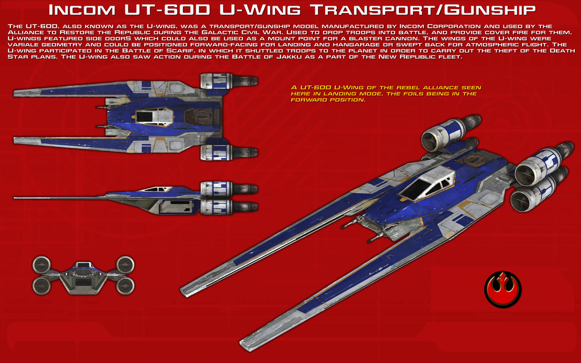
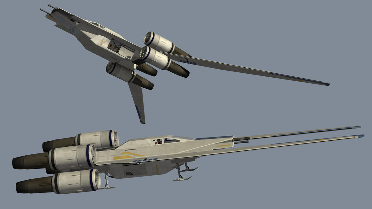
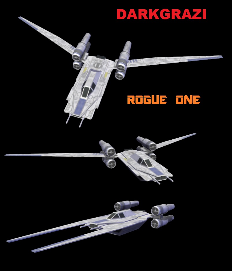
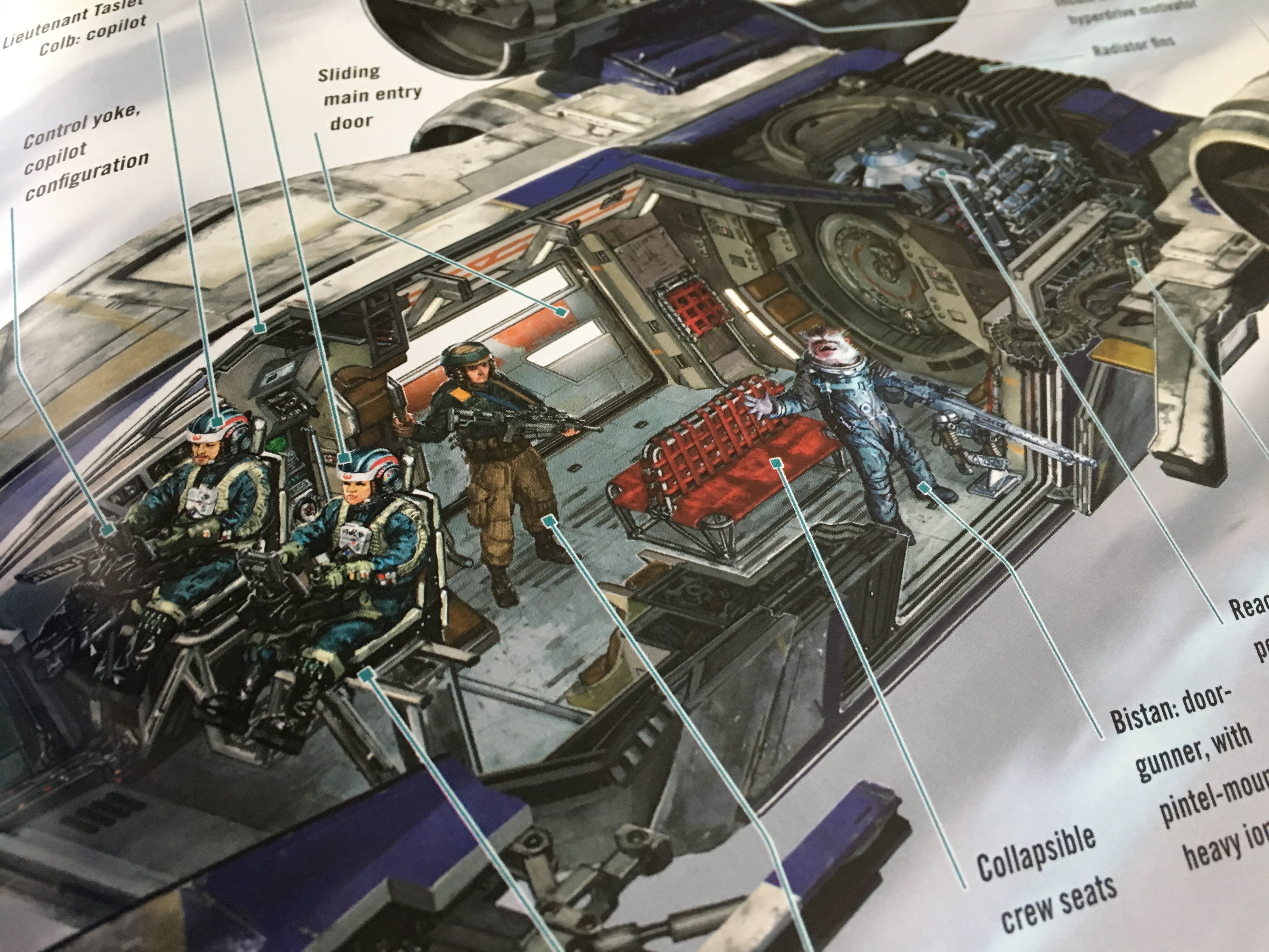
Here's a recent addition to the Star Wars Universe from Rogue One - A Star Wars Story: A UT-60D U-Wing Starfighter/Gunship.
Used by the Rebel Alliance to transport strike teams into hostile areas, the heavily armed U-wing provided combat support during the retrieval of the Death Star plans at the Battle of Scarif.
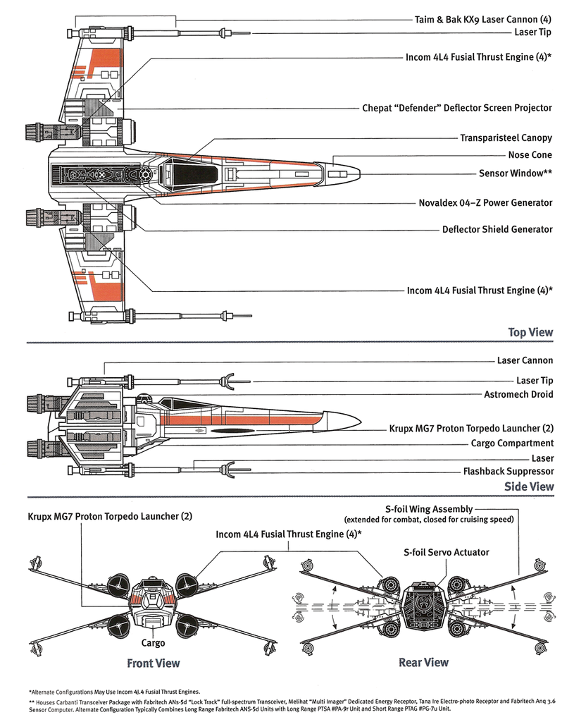
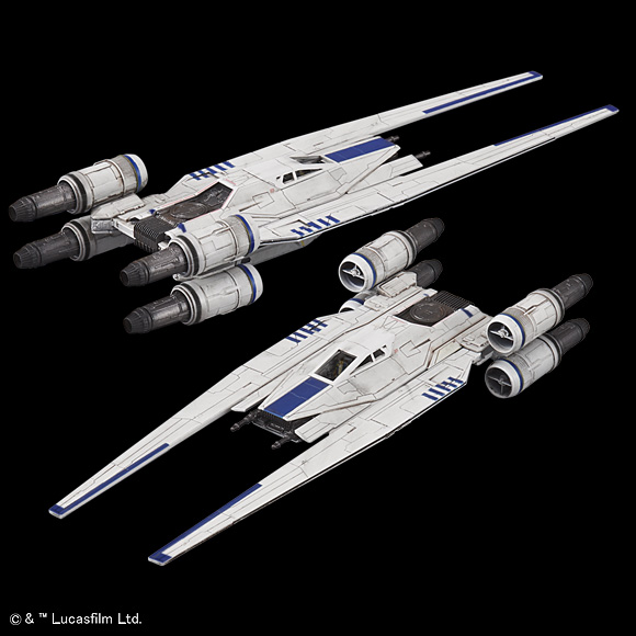
Manufactured by Incom Corporation, the same company that created the famed X-Wing fighter, the U-wing also has a distinctive S-foil that can be deployed towards the rear in flight/attack configuration.
I originally planned to integrate a folding mechanism for the S-foil in this particular build but the extended fuselage was too thin to support a dowel to pivot the wings. I ended up making two versions of the U-wing, in flight configuration and with the S-foil in retracted position. Nevertheless, the build was challenging with the open-door passenger compartment integrating some details like the collapsible passenger seats and reactor access doors in for the retracted S-foil version.
Like all previous builds, prospective modellers can download the included .pdf plans I used for this project. I hope everyone would build more U-wings. The Alliance needs it!
Step 1: Materials and Tools


Just a few tongue depressor sticks for the fuselage, wings and passenger/cargo compartments, regular sized popsicle sticks for the main engines and wooden dowels for the engine exhausts were used for this project. Most of the smaller parts came from my spares box.
Tools used were as follows:
- Dremel 3000 with the following attachments and accessories:
- Dremel's workstation and flex tool shaft
- Coarse and Fine Drum sander
- Fine disc Sander
- Standard & reinforced cut-off wheel
- #125, #118 & #193 High speed cutters
- #9934 Structured tooth tungsten carbide cutter
- #953 & #8215 Aluminum oxide grinding stones
- #85622 Silicon carbide grinding stone
- #7134 Diamond wheel point
- Ball-shaped grinding stone
- Olfa hobby knife
- Fine tweezers
- Mechanical pencil
- Ruler
- Various Plastic Clamps
- Elmers White Glue
- Cutting mat
Step 2: Schematics and Images


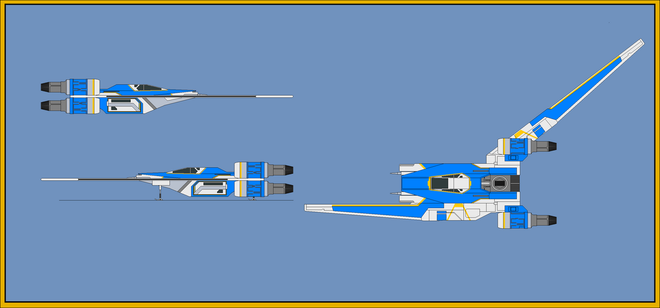
I was hoping to download a schematic of the U-Wing from the the-blueprints.com website but alas, it was not yet available.
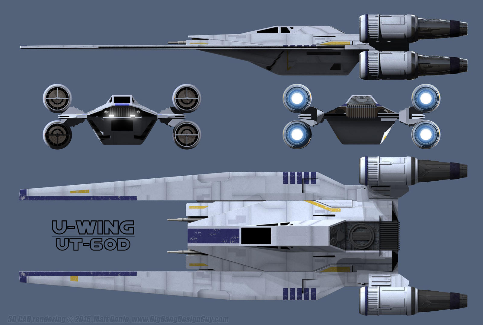
Instead, I used the schematic from deviantart.net. The size of the model was estimated from the image in photobucket showing a top-view scale of the U-wing in relation to the X-wing and Tie-fighter. The only usable image of the interior passenger/cargo compartment of the U-wing was from disneynerd.files.wordpress.com.
Links for all the images used for this project are:
http://photobucket.com/gallery/http://s1281.photob...
http://i730.photobucket.com/albums/ww307/Agent239...
http://photobucket.com/gallery/http://s1281.photob...
http://img00.deviantart.net/98d0/i/2016/280/e/6/u...
http://photobucket.com/gallery/http://s1281.photob...
http://www.thatsnomoon.info/uploads/2/5/4/1/25412...
http://photobucket.com/gallery/http://s1281.photob...
http://media.moddb.com/images/members/1/822/82176...
http://photobucket.com/gallery/http://s1281.photob...
https://disneynerd.files.wordpress.com/2017/01/im...
Again, my heart filled thanks to all donors of images to which there would be no popsicle stick projects. Thanks everyone!
Attachments

Step 3: Main Fuselage


From the printed deviantart schematics, a pattern from the top-view image was sketched on to a tongue depressor-sized popsicle stick.
From the pattern, I estimated the entire thickness of the fuselage to be three layers thick. The base layer was the size of the entire fuselage. The second layer defines the shape of the fuselage and the third layer supports the canopy of the starship. The second and third layers were beveled before lamination using a fine drum sander attachment. This reduced the need for heavy sanding after the three layers were glued together.
The three layers were laminated using white glue and clamped to minimize the spaces in-between layers. The fused piece was finished using a ball-shaped grinding stone (for the curved sides), fine drum sander and a #8215 Aluminum oxide grinding stone attachments on a moto tool.
The single layer canopy was shaped from a thicker, regular-sized popsicle stick using a #8215 Aluminum oxide grinding stone and fine disc sander attachment on a Dremel 3000. The #8215 Aluminum oxide grinding stone was useful for the angled shape of the canopy.
The finished canopy was glued on top of the finished, three-layer main fuselage.
I earlier mentioned that I ended up making two versions of the U-wing. Hence, this step was repeated for the second U-wing version. The same goes for the engine sub-assemblies. I had to fabricate eight (8) sets for the two versions.
Step 4: Engine Sub-assembly


Unfortunately, commercially available wooden dowels from the craft store was a little small for the main engines illustrated in the schematics. So I did the next best thing, build them from scratch.
Scratch building required laminating four (4) layers of regular-sized popsicle sticks with Elmers glue, grinding them with a coarse drum sander to shape the single piece into a dowel and finishing the dowel with a #8215 Aluminum oxide grinding stone attachment to make it smooth.
An intake hole was drilled and finished at the front end of each main engine using a #125 High speed steel cutter, a #9934 Structured tooth tungsten carbide cutter and a #953 Aluminum oxide grinding stone attachment on a moto tool. Each engine was detached from the dowel using a reinforced cut-off wheel attachment.
SAFETY TIP:Do not use the reinforced cut-off wheel to completely detach the engine from the dowel. Instead, leave a small connection and use an Olfa cutter to slice off the engine from the dowel. It's less dangerous than having the reinforced cut-off wheel run thru the entire dowel.
The available dowel from the craft store,on the other hand, was perfect for the engine exhausts of the U-wing.
After the length was traced from the schematic, the dowel was shaped using a fine drum sander attachment on a moto tool. A hole was drilled at the end of the exhaust using a #125 High speed cutter to make a pilot hole and finished with a #7134 Diamond wheel point and a #118 High speed cutter attachment. Again, each exhaust was detached from the dowel using a reinforced cut-off wheel to slice it partially and cutting it off completely with an Olfa cutter.
To model the nozzle for the exhaust, a line was scribed near the end of each exhaust using a standard cut-off wheel attachment.
Each engine and exhaust fabrication step was repeated for each of the eight engine sub-assemblies for the two versions for the U-wing.
Step 5: Passenger/Cargo Compartment for the Retracted S-Foil Version


The most difficult part of the build was the fabrication of the Passenger/Cargo compartment for the Retracted S-Foil version of the U-wing. This was due to the incorporation of small details like the passenger collapsible seats and reactor access doors. These were slightly visible via the modeled open doors of the compartment in the completed model.
I started of by tracing the shape of the passenger/cargo compartment as shown in the Deviantart schematic. Each side of the compartment was cut from a separate piece of tongue depressor-sized stick using an Olfa hobby knife. Openings for the sliding door were cut-out from each of the two sides using a #125 high speed cutter and a #7134 Diamond wheel point attachment for pilot holes for the four corners and a #85622 Silicon carbide grinding stone to grind out the sides. A #193 High speed cutter attachment was useful in shaping the sides of the door cut-outs.
After finishing the sides and rear of the Passenger/Cargo compartment and cutting the three-piece floor to shape, it was a matter of gluing the individual pieces with Elmers glue and allowing the joined pieces to dry.
For the sliding doors of the compartment, spare, thin popsicle sticks from my spares box were used. A pattern for the door was traced and cut using an Olfa cutter. The doors were glued to the rear part of the Passenger/Cargo compartment.
Four (4) regular-sized popsicle sticks made up the rear-mounted reactor access door. From the disneynerd.files.wordpress.com image, the access door was circular and connected to the rear bulkhead of the Passenger/Cargo compartment. To model this, a hole was drilled on the first layer using a #125 High speed cutter and #9934 Structured tooth tungsten carbide cutter attachment on a Dremel 3000 moto tool. The finished piece was glued to the other three layers to make up the complete rear bulkhead with the reactor access door. Finally the rear bulkhead sub-assembly was shaped using a coarse drum sander attachment and finished with a fine disc sander attachment on a moto tool. A tiny piece from a dowel provided some details to the otherwise plain, circular door of the rear bulkhead. The completed rear bulkhead sub-assembly was glued to the rear of the Passenger/Cargo compartment.
For the collapsible bench seat backrest, a tiny popsicle stick scrap was cut and glued at the center aisle of the Passenger/Cargo compartment.
It was at this point that I realized that I forgot to pre-cut windows for the sliding doors before I glued it to the sides of the Passenger/Cargo compartment. For the windows ,I used a #7134 Diamond wheel point attachment to cut a slit into the already mounted doors.
Finally, with the backrest in place, more scraps were cut and shaped for the passenger seats using a hobby knife. These were carefully glued one on each side of the backrest. The seats were glued in such a way that it appeared suspended with only the backrest supporting it. Glad that was over and done with!
Step 6: Completing the U-wing With Retracted S-Foils


The unique characteristic of the U-wing with the retracted S-Foil was the illusion that the wings are part of the fuselage. This made the U-wing in this configuration easier to fabricate (with the exception of the Passenger/Cargo compartment!).
The combination S-foil, extended rear fuselage was from a long, single tongue depressor-sized stick cut into shape with an Olfa cutter. The leading and trailing edge of the S-foil was shaped using a fine drum sander attachment and finished with a fine disc sander attachment on a moto tool. Each finished S-foil was glued to each side of the main fuselage from Step 3.
Four (4) engine mounts were cut from regular-sized popsicle sticks and shaped using a fine drum sander attachment. Two (2) top engine mounts were glued at the top, rear end of the S-foil. Each engine was glued to the engine mount using a scrap tongue depressor stick to prop up the engine while the glue dries.
TIP:The method used to bind materials with contact cement also holds true when using Elmers white glue. By applying small amounts of glue to surfaces of materials to be joined and allowing the white glue to dry a little bit before binding the pieces, the materials were easier to join with a lot less play until the glue totally dries. This method was helpful for joining materials with very little contact surface between the two pieces.
With the top engines and engine mounts in place, I turned the entire model upside down and made a special jig that will support the bottom engines to the engine mounts while the white glue dries. The bottom engine mounts were glued to the rear ends of the S-foils. A bevel to increase the contact area between the engine and engine mount was made using a fine drum and disc sander attachment on a moto tool. The bottom engines were glued to the engine mounts with the special jig supporting the engine until the glue dried.
For added detail, a circular shield generator was drilled from a dowel using a a #125 High speed cutter and #9934 Structured tooth tungsten carbide cutter attachment on a Dremel 3000 moto tool. The piece was detached from the dowel with a standard cut-off wheel attachment. The circular shield generator was glued on top of the fuselage directly behind the cockpit canopy. Finally, a rectangular detail was cut from spare popsicle sticks and glued at the center of the circular shield generator.
The Passenger/Cargo compartment from the previous step was glued at the bottom of the fuselage to complete the major sub-assemblies.
I seemed that more details were required to cover the huge, gaping holes of the front engines. With more tiny scraps from my scrap box, intake fins for each of the four huge engines were fabricated. It turned out that the only thing needed to complete the U-wing with retracted S-foils was the installation of the twin cannons. This was after I struggled to align the intake fins for each of the four (4) engines. What a bummer....
Step 7: Completing the U-wing With Deployed S-Foils Version


For this version of the U-wing, the distinctive feature was the swept-back wings reminiscent of a gannet diving for fish.
The Passenger/Cargo compartment was also easier to fabricate than the retracted S-foil version with open doors and added details. The only details for the Passenger/Cargo compartment on this version were the etched doors and windows on the sides of the sub-assembly.
For the Passenger/Cargo compartment, six (6) layers of tongue depressor-sized sticks were laminated using Elmers glue. Plastic clamps held the pieces together while the glue dries. The clamps reduced spaces between the layers.
The shape of the Passenger/Cargo compartment was traced using the Devantart schematics and shaped using a coarse/fine drum sander and #8215 Aluminum oxide grinding stone attachment on a moto tool. Details for the sliding door and slit windows were scribed at the sides of the Passenger/Cargo compartment using a standard cut-off wheel, #7134 Diamond wheel point and a #193 High speed cutter attachment on a Dremel 3000.
Scrap tongue depressor-sized sticks were cut and glued to the rear quarter sides of the main fuselage where the S-foils pivot. The extended main fuselage connected the engine and engine mount assembly to the major sub-assemblies of the U-Wing.
Engine mounts similar to the retracted S-Foil version in the previous step were glued at the top, rear end of the extended main fuselage. Plastic clamps held these in place while the white glue dried. The edges were also beveled using a fine drum sander attachment to increase the contact area of the engine mounts with the engines. The engines were glued to the top mounts supported by spare popsicle sticks until the glue dried.
One end of the long S-foil was trimmed at an angle and glued to the front of the extended main fuselage with the wing angled towards the rear of the U-wing. The U-wing in attack configuration was finally taking shape after gluing the other S-foil at the opposite side of the extended fuselage.
With the S-foils in place, the entire assembly was turned-over so the bottom engine mounts could be glued in place. The engines were glued in place after grinding the edges of the bottom engine mounts at an angle to increase the contact area.
The Passenger/Cargo compartment was glued below the main fuselage with the more angular side oriented towards the front of the starship. Finally, the twin cannons were glued at the slot in front of the U-wing to complete the build. Captain Cassian Andor and K-2SO would love this project!


