

Introduction: Servo Ramping and Soft-Start


This Instructable is about how to use a microprocessor to drive servos. Easy. Right? You learned it at your mother's knee.
Well it's not quite that straightforward. This isn't a "project", it's some notes on better ways of controlling servos and some code you can use in your own projects.
When I look on the web, I find lots of people asking the same questions
- "how do I ramp the servo speed up/down?"
- "how do I make servos move in unison?"
- "how do I do soft-start for servos?"
- "how do I not break my servos?"
The questions keep popping up but I don't see any answers.
So here's my take on the problem. There's
- an algorithm for doing ramping of a single servo
- an algorithm for ramping servos in unison
- how to measure how hard a servo is working
- an explanation of how to make servos "relax"
But unfortunately not
- how to do a soft start
I'm working on a robot-arm project and also an "android" head. I'll publish them as Instructables Real Soon Now. Both have quite high inertia and both will benefit from ramping servos. They'll also benefit from moving servos in unison.
Step 1: Ramping the Servos


When you send a command to a servo, you're telling it where to go. A standard servo goes there as fast as it can. If it's driving a load with a lot of inertia - like turning the head in my android-head project - that can require a large torque which might damage the servo gears. When you try to stop the head turning, it could well overshoot leading to oscillation.
If I tell a robot arm to move the shoulder to angle A, the elbow to angle B and the wrist to angle C, then I'd like all the joints to arrive at their target at the same time The fingertips won't travel in a straight line but the line will be a lot straighter than if the joints move independently.
The "brain" of the robot (an ESP32cam in the android-head and the robot arm) sends target positions to the servo controller (an Arduino Nano) over a serial line and we want the controller Nano to make the servos go to that target in a sensible way.
Could you use a PID controller? In theory, a PID requires feedback from the servo - which we don't have. The arduino has no idea what the servo is actually doing. But we could assume that the servo is where the command pulses tell it to be. The drawback is that PIDs are notoriously difficult to "tune" - to find the right values of Kp, Ki and Kd parameters. The parameters depend on the inertia of the system and we don't know that. I've done PIDs for big industrial robots but they're overkill for a hobby project.
A compromise is to limit the maximum acceleration - amax - and maximum velocity - vmax - of the servo. It's a kludge but by choosing reasonable values for amax and vmax you can get the servo to behave reasonably under most circumstances.
To move the position of the servo - p - from where it currently is to a target position you want to
- accelerate at amax
- coast at vmax
- decelerate at -amax
The graph of velocity has a trapezoidal shape. Velocity ramps-up, stays constant then ramps down.
We divide the time into "time-steps" of, say, 50mS. At each step, we decide what new position command to send to the servo. You might want to combine the ramp "time-steps" with the 20mS period of the position commands but I couldn't be bothered with that complication.
If you've only got a single servo, the maths is easy. We have
- p: current position
- target: required position
- v: current velocity
- vmax: maximum velocity
- amax: maximum acceleration
At each time step:
   p0:=2*v + abs(v)*v/(2*acc);
   v:=v+sign(target-p-p0)*amax;
   v:=constrain(v,-vmax,vmax);
   p:=p+v;
p0 is the distance it will need for the servo to come to rest given its current velocity. So what the equation says is "if you're going to overshoot then decelerate otherwise accelerate; but never exceed the maximum velocity". I suppose it's a kind of feedforward control.
A further problem comes when you have several servos. What you want is for them to act together. You want them all to arrive at their targets at the same time. But the servos might have different amax and vmax and will have different distances to travel to their targets. (I'll assume that when they reach their target they come to rest.) I can find nothing on the web about multiple servos acting together - either with PIDs or ramping.
In the case of a head, the eyes have high vmax and amax while turning the head has low vmax and amax. A robot arm will have higher vmax and amax at the elbow than at the shoulder and higher still at the wrist. If the head is not moving then the eyes can move fast but if the head and eyes are simultaneously to given targets, you want both to arrive at their target at the same time as though the eyes were tracking the target (neither the Nano nor the ESP32cam can do real-time visual tracking).
If all the servos start at rest, it's not too difficult to get them to act together. But it they're already moving when a new target command arrives and the servos have different amax and vmax then there is no "correct" solution. I tried a large variety of different algorithms and all had faults. I can't find any papers on the subject.
The best I have come up with is this: Each servo [i] has a maximum acceleration - amax[i] - and maximum velocity - vmax[i]. But within each "move" (from current position to target) you can further restrict the maximum acceleration and velocity: amax_1[i] and vmax_1[i]. At each timestep, you choose a number g[i] so that
vmax_1[i] = vmax[i] * g[i];
amax_1[i] = amax[i] * sqr(g[i]);
then apply the algorithm above.
How do you choose g[i]? It's in the range 0..1 and must be smaller when you want to slow down a "fast" servo so it keeps pace with a "slow" servo. After a lot of experiments, the best formula for g[i] that I found is:
  t[i] = time_to_target of servo[i] assuming amax and vmax
  tmax = max of all the t[i]
  g[i] = t[i]/tmax
What is the time-to-target? It depends on amax and vmax. It amax is high, then time-to-target is low. It vmax is high, then time-to-target is low. I chose the rather arbitrary formula
time_to_target = max( time_assuming_vmax, time_assuming_amax)
time_assuming_vmax is the time to get from p[i] to target[i] if the servo moves at vmax:
time_assuming_vmax = abs(target[i] - p[i]) / vmax[i]
time_assuming_amax is the time to get from p[i] (with velocity = v[i]) to target[i] (with velocity = 0) if the servo moves at amax (ignoring vmax):
   sign1 = sign(sqr(v[i]) + amax[i]*2*(2*abs(v[i]) + sign(v[i])*(p[i]-target[i])));
   time_assuming_amax = (sign1*abs(v[i]) + sqrt(abs(2*sign1*v[i]*abs(v[i]) + 4*amax[i]*(p[i]-target[i]))))/amax[i];
(I'd hate to have to explain exactly where that formula came from. I started from first principles, assumed all the possible starting conditions, then used Mathomatic to tidy up the equations.)
The algorithm uses floating-point maths which is slow. Right? At this point, you'd normally think about turning it into integer maths. Many of the numbers are quite small - a typical amax of a "slow" servo might be 0.01 - so you multiply each value by a scale factor - 100 or 1000 - then do the arithmetic using integers. You choose the scale factor so that it's big enough to give you enough precision with small values but not so big you get integer overflow. Working through it, I found I'd have to use long ints (4 bytes).
The speed of long int and float arithmetic on a Nano is approximately
- + - long int 2 uS float 8 uS
- * long int 5 uS float 10 uS
- / long int 40 uS float 31 uS
So floating-point takes about twice as long except that division is faster - presumably because it's 24-bit.
The algorithm has
- 14 add/subtract
- 16 multiply
- 5 divide
Which gives a total time per servo of
- long int 308 uS
- float 427 uS
In practice, the longint time would probably be greater than the float time because of all the extra arithmetic of the scaling factors. So just use floats. A surprising result - it's not what you're taught at school.
Step 2: Arduino Code


The attached Arduino code implements the algorithm and adds a few extra tweaks.
The algorithm as I described it oscillates if the acceleration is set to high values - above 2.0. A reasonable value for a robot arm or leg would be 0.01 but an eyeball can accelerate really fast. The tweaks help reduce overshoot and hence reduce oscillation. The code also allows special cases of
- Amax = 0: go immediately to Vmax
If you don't want to limit the velocity, set Vmax to a high value, e.g. 2000. With Amax=0 and Vmax=2000, the servo will immediately to the target
The MoveServos() function is called from the main loop. It runs the servo control algorithm every VelPeriod milliseconds (currently 50mS). If two or more targets are set then MoveServos() adjusts the acceleration and velocity so both arrive at same time. At each time-step, each servo asks itself:
- where am I now
- where do I want to be
- how long will it take all my group to get there
- so how fast should I move?
Although you often want servos to move in unison, sometimes you don't. In the case of my android head, these servos should move as a group:
- head up/down
- head left/right
- eyes up/down
- eyes left/right
I want them to move as a group because if I tell the head to turn to the left while the eyes to turn to the right, I want it to look as though the eyes are tracking a stationary object. (Visual processing isn't fast enough for them to do real tracking.) If the head stays still then commands to the eyes should move them very fast.
But these servos are not part of a group; they move independently of each other and the other servos:
- jaw open/close
- eyebrows up/down
Similarly in a robot arm, there is a group of
- shoulder left/right
- shoulder up/down
- elbow up/down
- wrist up/down
But these servos move independently:
- hand rotate
- fingers open/close
A quadruped robot like SpotMini would have several servo groups:
- group of 12 servos for legs
- group of 4 servos for arm
- 1 individual servo for hand rotate
- 1 individual servo for hand open/close
- group of 2 servos for head movement
(Of course, Boston Dynamics do robots properly. I'm talking about hobby robots here.)
So the attached Arduino code implements servo groups.
Group g=0 means that the servo is in no group at all - it acts independently, otherwise
- g=1: the servos in the group 1 act together
- g=2: the servos in the group 2 act together
- g=3: the servos in the group 3 act together
- etc.
- g=0: the servo acts independently
You would typically set up the speed and group of the servo once, e.g.
vmax[4] = 20;
amax[4] = 10.0;
group[4] = 1;
Then repeatedly set its target position:
target[4] = 1500;
But in this project, I'm assuming that the Nano is a dumb servo controller that receives serial commands from a master processor.
Attachments

Step 3: Serial Commands

In the attached code, the Nano receives commands through its serial port. Commands consist of a low byte and a high byte. The bits of those bytes are
      0nnnnnnn  n = low 7 bits
      10mmmsss  m = high 3 bits: set target of servo sss to mmmnnnnnnn0 + 500 microseconds (500..2547)
      1100msss  m = high bit: set max velocity of servo sss to mnnnnnnn microseconds per interval
      1101msss  m = high bit: set max acceleration of servo sss to mnnnnnnn microseconds per interval
      11100sss  servo sss is in group n
For instance, to set the target position of servo 3 to 1234
           3 = 011 binary
           1234 = 10011010010 binary
you would send
      01101001  low 7 bits = 0x69
      10100011  high 3 bits and servo num = 0xA3
If you don't want to limit the maximum velocity, send a command to set vmax to 0. It will be translated into vmax = (a big number).
If two or more servos are in a group then you send the commands to the servos in turn. The first servo you send a command to may start moving but the other commands will soon follow and you shouldn't notice the delay. However, if one of the servos move much faster, you should send its command last. Remember: the code that receives the commands and the code to move the head execute asynchronously. So if you set amax=0 and vmax=0 then send a command to move the servo that means "go to the target instantaneously". The MoveServos() function may be called in the brief moment before the next command to move another (slower) servo arrives. If you're sending a group of commands, always send the slow servo commands first.
Step 4: Servo H-Bridge


Standard servos receive command pulses 1mS to 2mS long every 20mS (or maybe 0.6mS to 2.4mS depending on the model). There's a potentiometer which measures the position of the output shaft. There's then some analogue electronics which outputs pulses to an H-bridge controlling the motor. The width (and direction) of the H-bridge pulse depends on the width of the command pulse compared with the output from the potentiometer. It used to be done with 1960selectronics - quite clever. Of course, there are now chips like the AA51880 or the M51660 or the CMT5188.)
The 20mS gap between pulses allows the electronics to recover: I suppose a capacitor is recharging or something. (There are more modern "digital" servos that have different electronics. What I'm describing doesn't apply to them.)
There's one H-bridge motor pulse per command pulse. The H-bridge pulse starts when the command pulse stops. No-one seems to realise that. I've searched the web and I can't find it discussed anywhere. It has two consequences:
If you stop sending pulses, the servo "relaxes". It's as though the servo is switched off. The motor stops straining and you can back-drive it (maybe - take care). That's useful for robots. To save power, you don't have to switch off the power to the servos, just stop sending them pulses. The standby current is a few mA.
This code turns off the servo for 5 seconds:
 myservo.writeMicroseconds(position);
 myservo.detach();
 digitalWrite(ServoPin, LOW);
 delay(5000);
 myservo.attach(ServoPin);
The code in Servo.h seems to remember the last "position" command you sent to the servo and starts sending it again when "attached".
Secondly, it you measure the width of the H-bridge pulses, you can tell how hard a servo is working.
When you're developing a robot, you often get the commands wrong and the robot starts trying to destroy itself - they strip the teeth from the servo gears or break limbs. You can measure the H-bridge pulse width via a 1ohm resistor in the servo's power wire - either the 0V or 5V wire. The easiest way to see the pulse is with an Adruino's ADC. You don't measure the height of the pulse, just its width. So if the robot's legs are jammed, the H-bridge pulse might be (e.g.) more than 5mS long for 3 consecutive pulses. If you see that, stop sending servo pulses. I've saved several servos and robots that way.
If you're controlling, e.g., six servos, you will want to measure each one's H-bridge pulse individually. You could put a 1ohm resistor in the power line of each servo - that's six resistors going into 6 ADCs - a lot of pins.
Or you could use one resistor for all of them. Use a bit-banged pulse generator rather than Servo.h library. Send a command pulse to the first servo using
       digitalWrite(ServoPin,HIGH);
       delayMicroseconds(Position);
       digitalWrite(ServoPin,LOW);
Wait a few microseconds (0.2mS maybe) so the H-bridge will have gone high and time how long until the H-bridge goes low.
       delayMicroseconds(200);
       measure time until current goes low.
Then move on to the next servo and do it again. Visit each servo in a round-robin. I've managed to control 8 servos that way. If you need more servos, the loop gets too long (more than 20mS) and you'll need a second resistor and ADC. Or preferably a second microprocessors - processors are cheap.
In your round-robin, wait at least 20mS for each loop. If you send command pulses too fast, the servo's electronics has not recovered and will send the wrong pulses to the motor H-bridge.
I have code that runs a biped robot like that. When I was making the robot, I often got the legs tangled and the "servo saver" hardware/software was a great asset. (I could post the code here but it's in an obscure BASIC dialect and runs on a PIC.)
Step 5: Soft Start

When a microprocessor starts up, the processor doesn't know where the servo is. It will be wherever it was when the robot was last turned off. So when the processor sends the first position commands (pulses) to the servo, the servo goes to that position as fast as it can. That might damage the servos or your robot. It would be much nicer if the servos went slowly to their "initial" positions. If you look on the web you can see a lot of people asking "how do I stop that initial jump?". I reckon the answer is that you can't without modifying the servo.
The Servo.h library sends commands to the servos using the Arduino's PWM hardware. It starts sending pulses as soon as you "attach" the servo and the first pulse is to the default position - 1500uS, i.e. the centre. You might then tell Servo.h to go to the servo's initial position. You can see the servo twitch. Don't do it that way. Always set the position before doing the "attach":
   myservo.writeMicroseconds(init_pos);
   myservo.attach(3);
But the servo will still go to init_pos as fast as it can. How can you slow it down?
One suggestion on the web is to gradually increase the voltage to the servo. That doesn't work. The servo is still pretty strong at 4V but below that, the servo's electronics just don't work well. So as you decrease the voltage to the servo, say from 6V down to 1V, the servo works just fine down to, say, 3.5V (depending on the make) then stops working or goes crazy. It gets a little weaker but doesn't move noticeably more slowly.
Putting a resistor in the supply line doesn't work either. You might think that the electronics has a smoothing cap and so would continue to see 6V while the motor draws less current during the H-bridge pulses. It doesn't work. The varying supply voltage confuses the electronics and the servo goes crazy again. I've even had a servo start to rotate continuously.
Could we use less frequent pulses to gently start the servos from rest as described in the previous step? Then gradually increase the pulse frequency to 50Hz?
Here's some Arduino code which sends a command pulse every second:
void setup() {
 pinMode(ServoPin, OUTPUT);
}

void loop() {
 while (true) {
   digitalWrite(ServoPin,HIGH);
   delayMicroseconds(1500);
   digitalWrite(ServoPin,LOW);
   delay(1000);
 }
}
(Notice how I've had to bit-bang it. The PWM hardware can't run that slowly.)
Wire-up a servo and gently push on the servo horn with your finger. You'll feel the individual pulses.
Does it work for a soft-start? No. Each pulse is quite strong and produces a big jerk in the robot.
You can hack the servo to read the voltage of the potentiometer then your start-up code can send commands to gradually move the servo to the correct initial position.
But hacking servos is a pain, particularly if your robot has lots of them. You can buy them ready-hacked (1, 2, 3, 4, 5) for two or three times the price.
Or use serial servos which are even more expensive.
So how do you do soft-start without hacking the servo? Darned if I know.
Step 6: Conclusion

The right way to control a robot's joint is to use a PID. The processor always knows the current joint angle and the PID is tuned to the mechanics of the robot. That's the way "real" robots do it. They also do inverse kinematics and force-feedback and so on. If you're using hobby servos, you can do none of that. Measuring the H-bridge pulse-width gives you some idea of the force but not enough to do feedback-control.
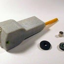
If your robot has inertia then you need to start its movement slowly - the servo's velocity should ramp up - so as not to damage the servo's gears. Once it's moving, the robot will have momentum so you should bring it to rest by ramping down the velocity. If you don't ramp down, the joint will overshoot, the servo will correct itself and start oscillating. If the robot is holding a heavy weight then oscillation will be even more likely. In the cheap robot arm shown above, I've added damping washers to reduce oscillation.
The video above shows the servo controller in action. The eyes servos usually move at full speed so the eyes are fast. But the eyes are in a group with the neck servos. The neck servos move more slowly and their velocity ramps up/down. So if the neck is moving and a command is sent to the eyes then the eyes also move slowly so it looks like they "track" along with the head turning.
You might be wondering why I'm only using 6 pins and they are pins 3, 5, 6, 9, 10, 11. Those are PWM pins and I thought maybe I could use PWM to do something clever with the servos. It turns out I couldn't do anything that the servo.h library can't do.
According to the Servo.h library, you can use up to 12 servos on a Nano. It is usually assumed that they can be on pins D2 to D13 but I can see nothing in Servo.cpp that says they can't be on D14 to D19 (i.e. A0 to A5). I haven't tried it. In Servo.h, MAX_SERVOS is defined to be 12. There's nothing to suggest that MAX_SERVOS can't be bigger; it may slow down the refresh period but that's not a big problem (see above). If you want more servos with a Nano, you'd probably be better using my ramping code to drive a PCF8574 module. Or use an Arduino Mega with up to 48 servos.
And finally, if you find out how to do a soft-start, please do tell me.

Second Prize in the
Microcontroller Contest


![Tim's Mechanical Spider Leg [LU9685-20CU]](https://content.instructables.com/FFB/5R4I/LVKZ6G6R/FFB5R4ILVKZ6G6R.png?auto=webp&crop=1.2%3A1&frame=1&width=306)


