

Introduction: The Arduino / TFT LCD Connection


You say you want to hook up a TFT display to an Arduino? Are you joking?
No! For about the price of a familiar 2x16 LCD, you get a high resolution TFT display. For as low as $4 (shipping included!), it's possible to buy a small, sharp TFT screen that can be interfaced with an Arduino. Moreover, it can display not just text, but elaborate graphics. These have been manufactured in the tens of millions for cell phones and other gadgets and devices, and that is the reason they are so cheap now. This makes it feasible to reuse them to give our electronic projects colorful graphic displays.
There are quite a number of small cheap TFT displays available on eBay and elsewhere. But, how is it possible to determine which ones will work with an Arduino? And what then? Here is the procedure:
- ID the display. With luck, it will have identifying information printed on it. Otherwise, it may involve matching its appearance with a picture on Google images. Determine the display's resolution and the driver chip.
- Find out whether there is an Arduino driver available. Google is your friend here. Henning Karlsen's UTFT library works with many displays. (http://www.rinkydinkelectronics.com/library.php?i...)
- Download and install the driver library. On a Linux machine, as root, copy the library archive file to the /usr/share/arduino/libraries directory and untar or unzip it.
- Figure out how to hook up the hardware, i.e., which display pins are wired to which pins of the Arduino.
- Load an example sketch into the Arduino IDE, and then upload it to the attached Arduino board with wired-up TFT display. With luck, you will see text and/or graphics.
- With the display functional, you can then hack together a breakout board or plug-in shield.
- Finally, interface the display to your favorite Arduino project and write a sketch that adds colorful text and graphics to it.
Step 1: Parts Needed
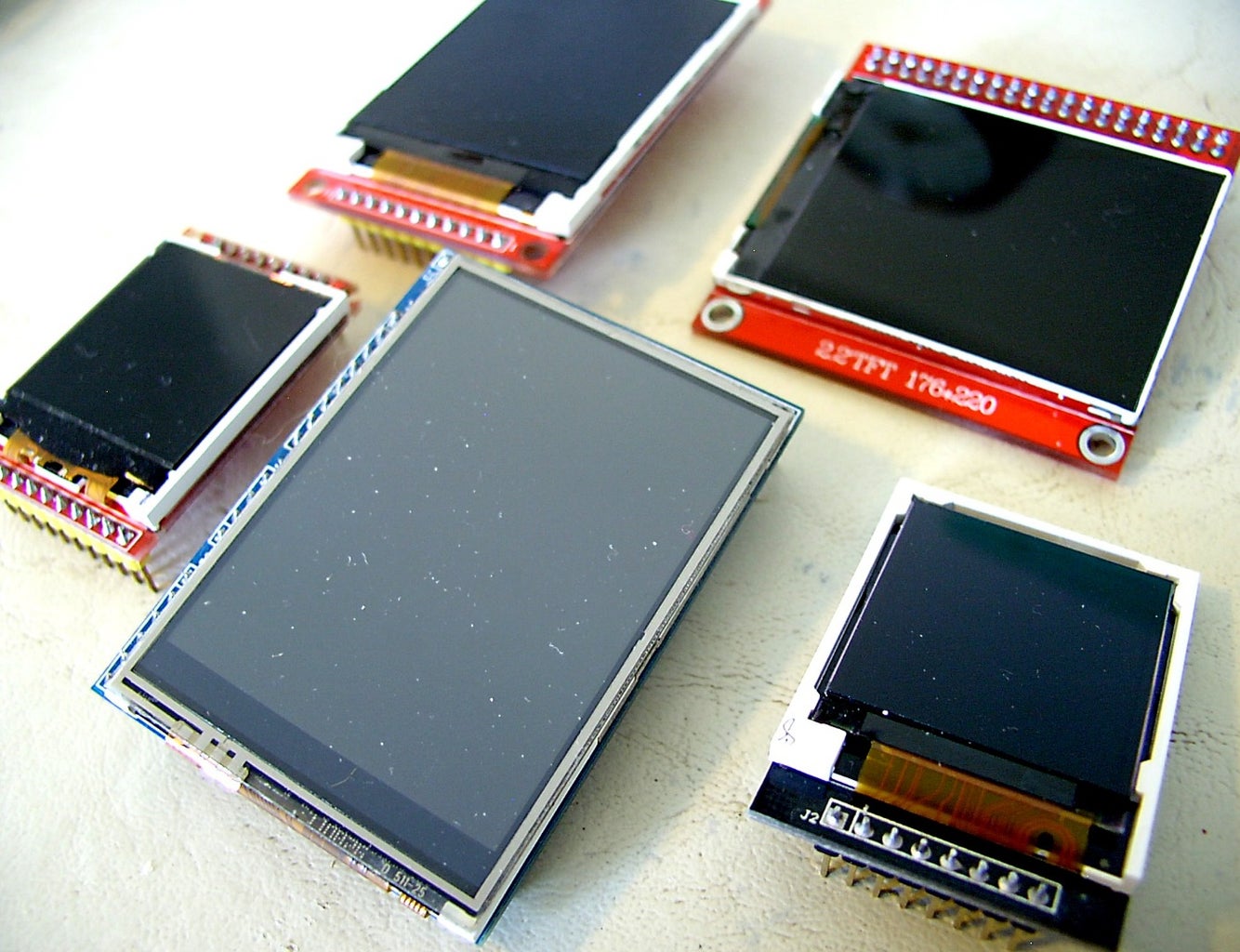


An assortment of cheap TFT LCDs ($20 ought to get you three or four)
Before you buy, check for Arduino compatibility!
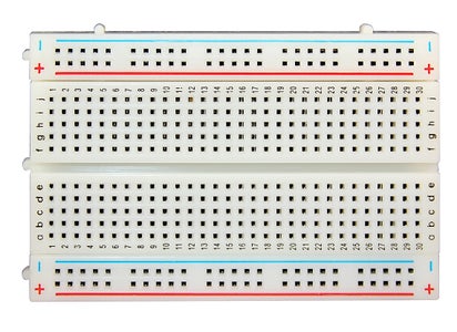
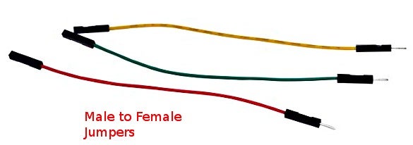
For prototyping and testing:
- A solderless breadboard male-to-male jumpers male-to-female jumpers 22 gauge insulated hookup wire, solid Graph paper, for planning and sketching wiring diagrams and layouts
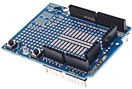
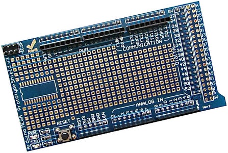
- One or more unpopulated protoshields, both for Uno and Mega/Due
- Female headers (these come in strips of 40)
- Solder (60/40, 1 mm or smaller)
- Arduino Uno or Hackduino -- wired for 3.3v operation, otherwise you'll need to mess with level shifters
- Arduino Mega2560 and/or Due
Tools
- Battery-powered soldering iron (the Hakko FX-901 is best of breed)
- A couple of sets (4 each) of decent rechargeable NIMH AA batteries. Note: Beware of cheap ripoff batteries from Hong Kong. These typically take only a 200 mA charge, and even an "intelligent" charger will not refresh them. Purple, blue, and green ones are suspect -- see picture and ... Link #1Link #2
- A good multitester and/or continuity tester
- A decent pair of needle-nose pliers
- Lead cutting shears (Plato makes good ones)
- Lots and lots of patience
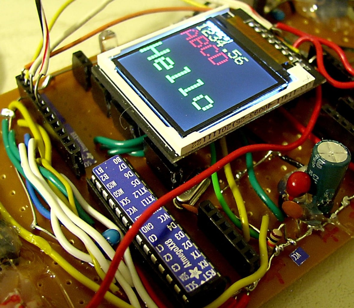
Step 2: Starting Out Easy: the ILI9163C Display


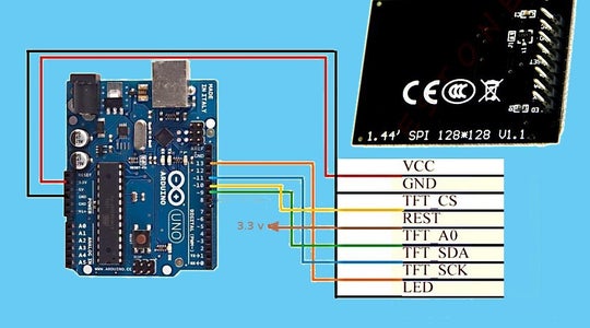
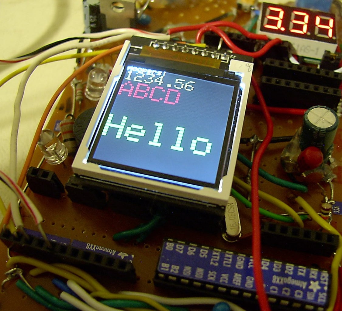
We'll begin with a simple one. The ILI9163 display has a resolution of 128 x 128 pixels. With 8 pins in a single row, it works fine with a standard Arduino UNO or with a Mega. The hardware hookup is simple -- only 8 connections total! The library put together by a smart fella, by the name of sumotoy, makes it possible to display text in multiple colors and to draw lines.
Note that these come in two varieties, red and black. The red ones may need a bit of tweaking to format the display correctly -- see the comments in the README.md file. The TFT_ILI9163C.h file might need to be edited.
These babies are quite cheap. See, for example, on eBay: $3.38, delivered all the way from China!
Hardware connections:
LCD pin              Arduino pin
-------              -----------
1 LED (backlight)    Vcc (3.3v)
2 SCK (slave clock)  D13
3 SDA (MOSI)         D11
4 A0  (DC)           D9
5 RESET              Vcc (3.3v)
6 CS (SS)            D10
7 Gnd                Gnd
8 Vcc                Vcc (3.3v)
As mentioned, sumotoy created a library to drive this display. Download the library from sumotoy's site.
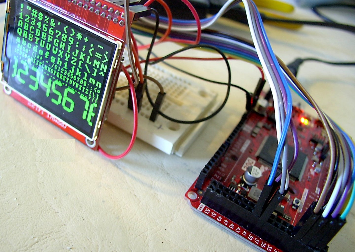
Step 3: The ITDB18SP Display
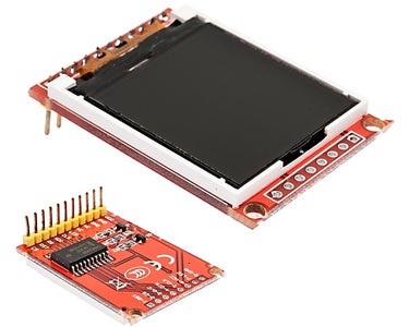
This one is a 1.44" display with a resolution of 128 x 128 pixels, and it uses an ITDB18SP driver.
It is 5-volt friendly, since there is a 74HC450 IC on the circuit board that functions as a level shifter. These can be obtained for just a few bucks on eBay and elsewhere, for example -- $3.56 delivered from China. It uses Henning Karlsen's UTFT library, and it does a fine job with text and graphics. Note that due to the memory requirement of UTFT, this display will work with a standard UNO only with extensive tweaking -- it would be necessary to delete pretty much all the graphics in the sketch, and just stay with text.
The hardware connections:
On 11-pin connector --
LCD Pin           Arduino Pin
 1 Vcc            Vcc (3.3v or 5v)
 2 Gnd            Gnd
 3 Gnd            Gnd or N/C
 4 N/C
 5 N/C
 6 LED            Vcc (3.3v or 5v)
 7 CLK            SCK  D13 / D52 on Mega or Due
 8 SDI            MOSI D11 / D51 on Mega or Due
 9 RS                  D9
10 RST reset           D8
11 CS             SS   D10 / D53 on Mega or Due
Note that the 8-pin connector is not used.
...
Example sketches for Uno and Mega/Due:

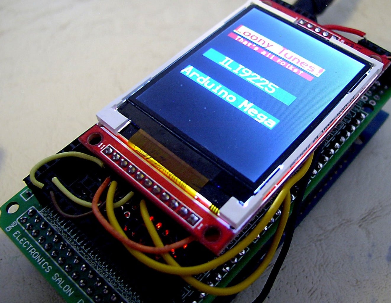
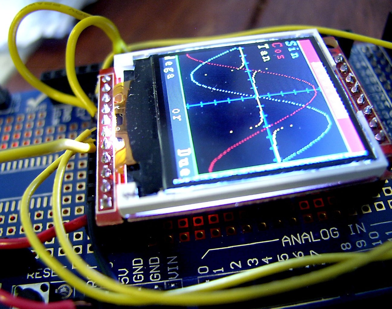
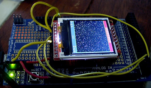
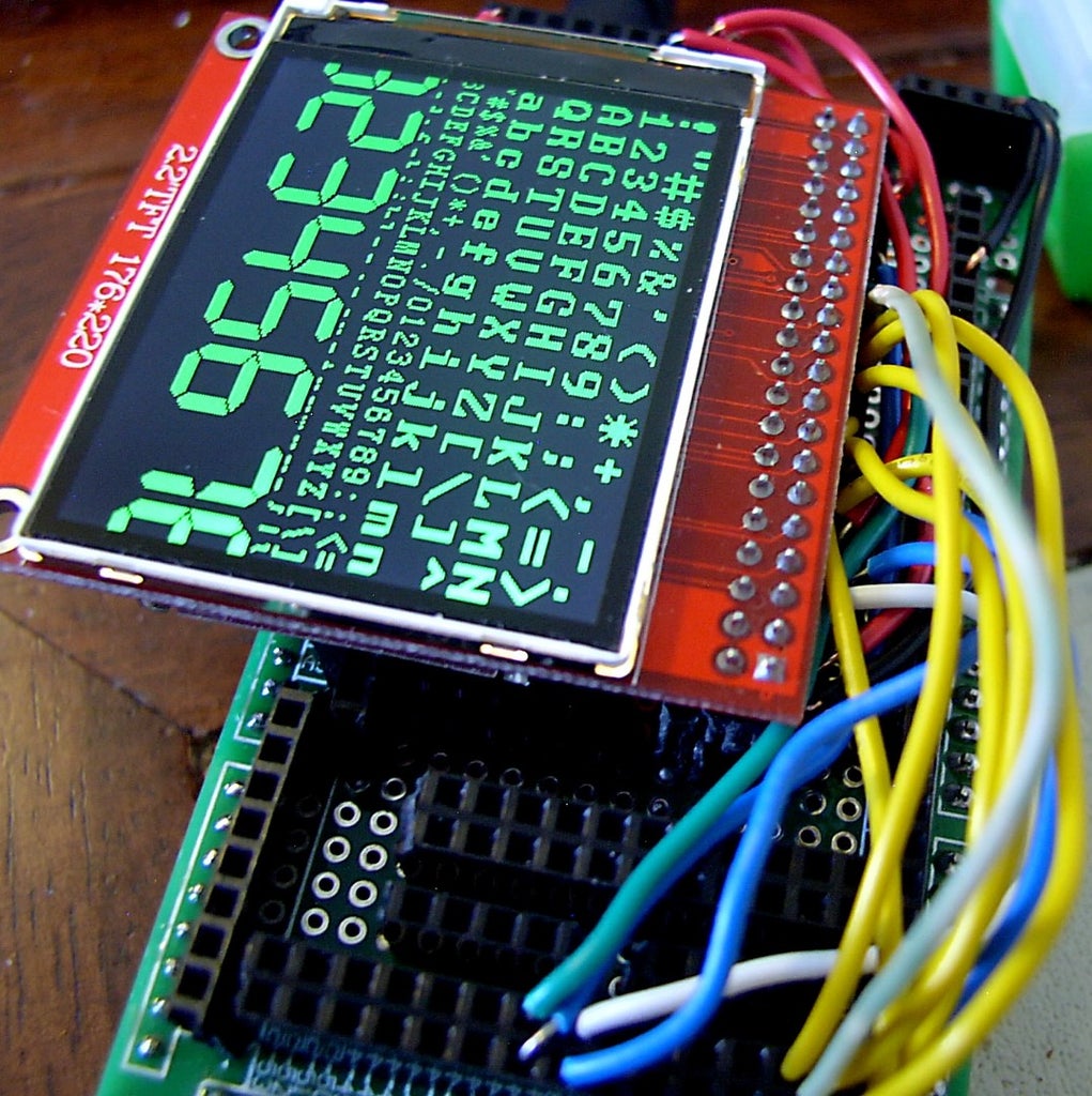
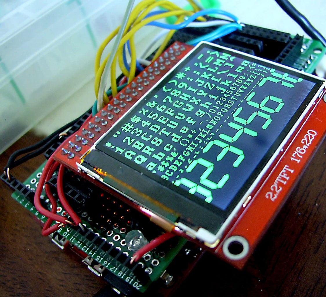
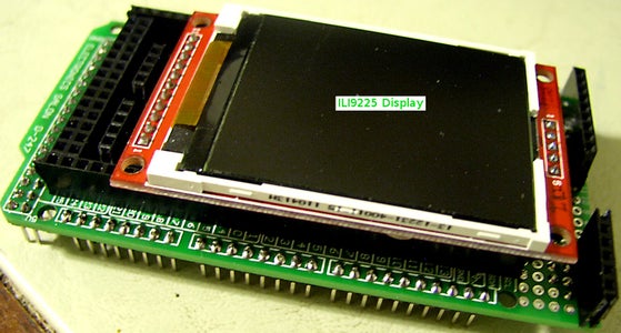
Step 4: The ILI9225 Display


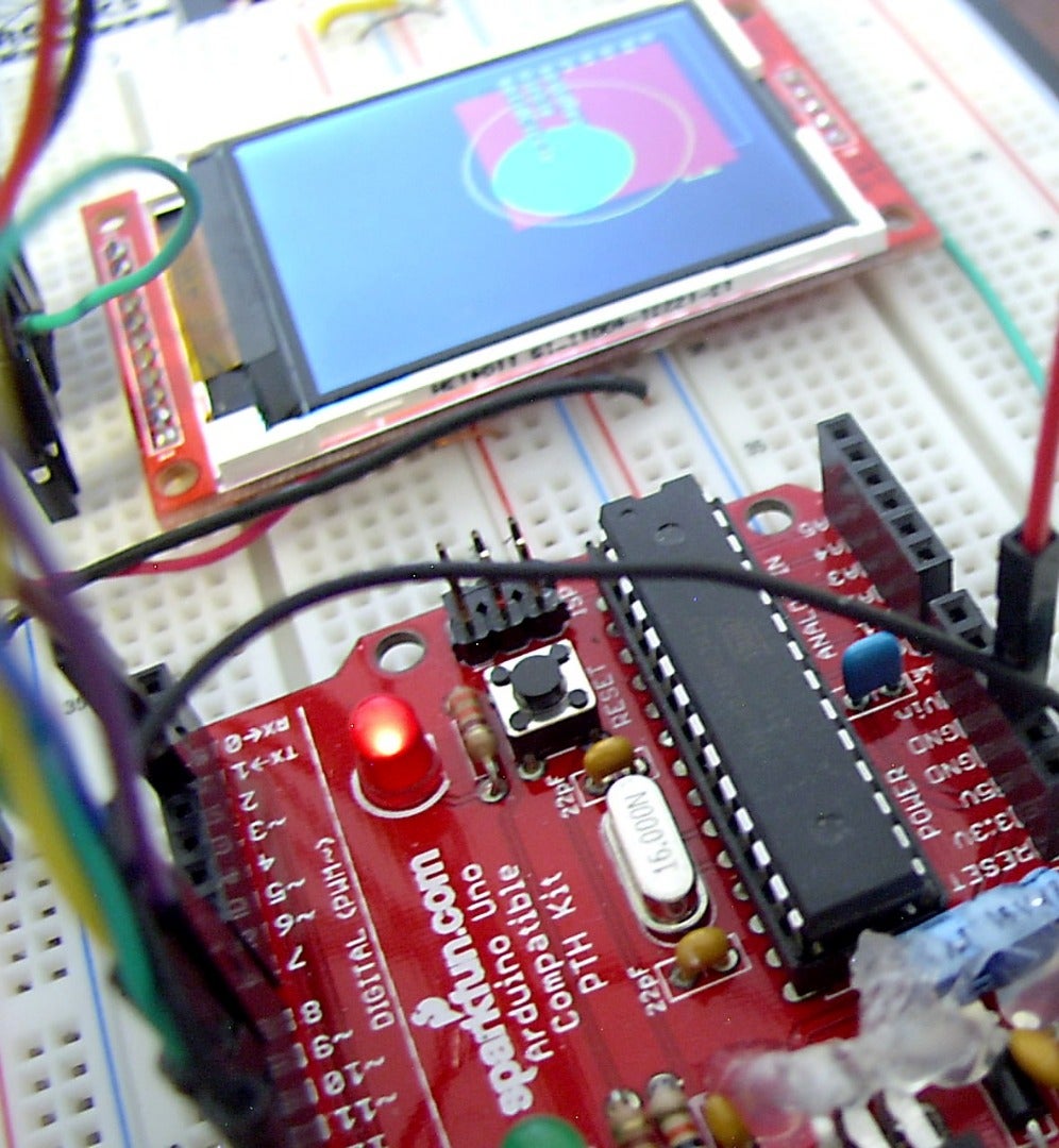
This baby has a row of 11 pins and a second row of 5 pins parallel to it
on the far side of the display. It has 220x176 resolution (hires!) and will accept either 3.3 or 5 volts. It will work hooked up to an Uno, and with a few pin changes, also with a Mega. The 11-pin row is for activating the display itself, and the 5-pin row for the SD socket on its back.
The hardware hookup:
LCD Pin                    Arduino Pin
-------                    -----------
 1  Vcc                    Vcc (5v or 3.3v)
 2  Gnd                    Gnd
 3  Gnd                    Gnd or N/C
 4                         N/C (not connected)
 5                         N/C
 6  LED (backlight)        D3
 7  CLK                    D13 (SCK)
 8  SDI                    D11 (MOSI)
 9  RS (register select)   D9
10  RST (reset)            D8
11  CS  (chip select)      D10
More information about this display
...
Example sketches for Uno and Mega
Attachments
Step 5: A 2.2" Display With Parallel Interface


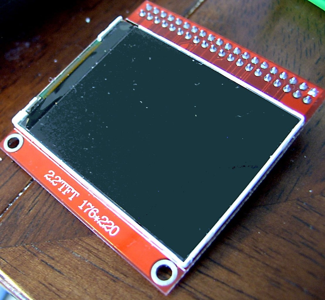
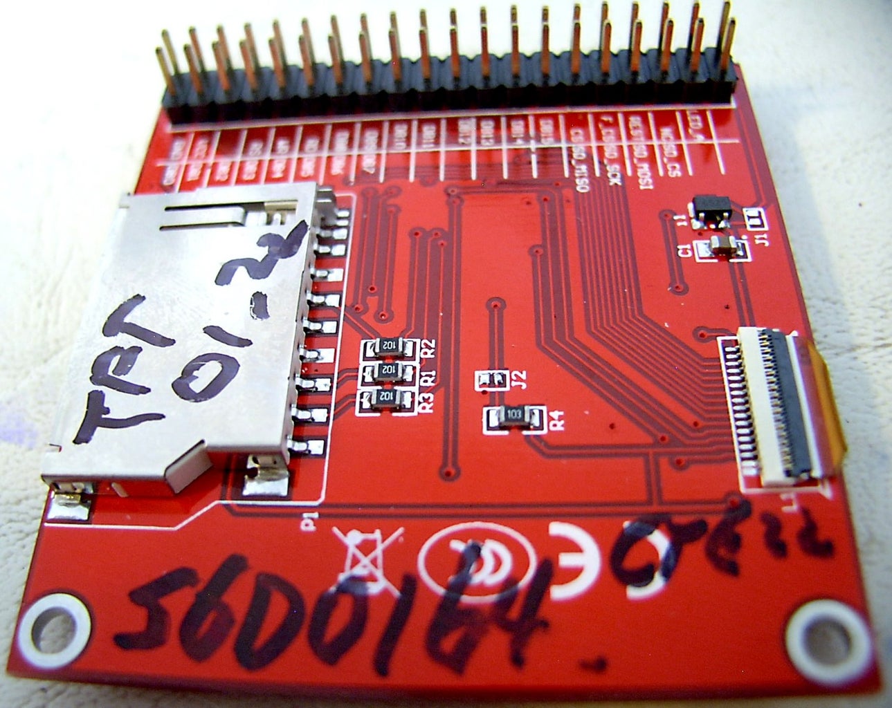
This one is a 2.2" (diagonal) display with 176x220 resolution and parallel interface. It has a standard ("Intel 8080") parallel interface, and works in both 8-bit and 16-bit modes. It uses the S6D0164 driver in Henning Karlsen's UTFT library, and because of the memory requirements of same, works only with an Arduino Mega or Due. It has an SD card slot on its back
It's a bit more expensive than the other displays we've discussed, see:
http://www.ebay.com/itm/310698848443
http://www.dx.com/p/elecfreaks-tft01-2-2-2-2-tft-l...
The hardware hookup is likewise a bit more complex. The pins are labeled on the back of the display.
LCD                     Arduino Mega/Due
----------------------------------------
DB08                    D22
DB09                    D23
DB10                    D24
DB11                    D25
DB12                    D26
DB13                    D27
DB14                    D28
DB15                    D29
RS (register select)    D38
WR (read/write)         D39
CS (chip select)        D40
RST (reset)             D41
Note that in 8-bit mode, the lower eight data lines, DB00 - DB07, are not used.
More information about this display.
The UTFT library.
An example sketch:
Attachments
Step 6: The SY-TFT240 Display
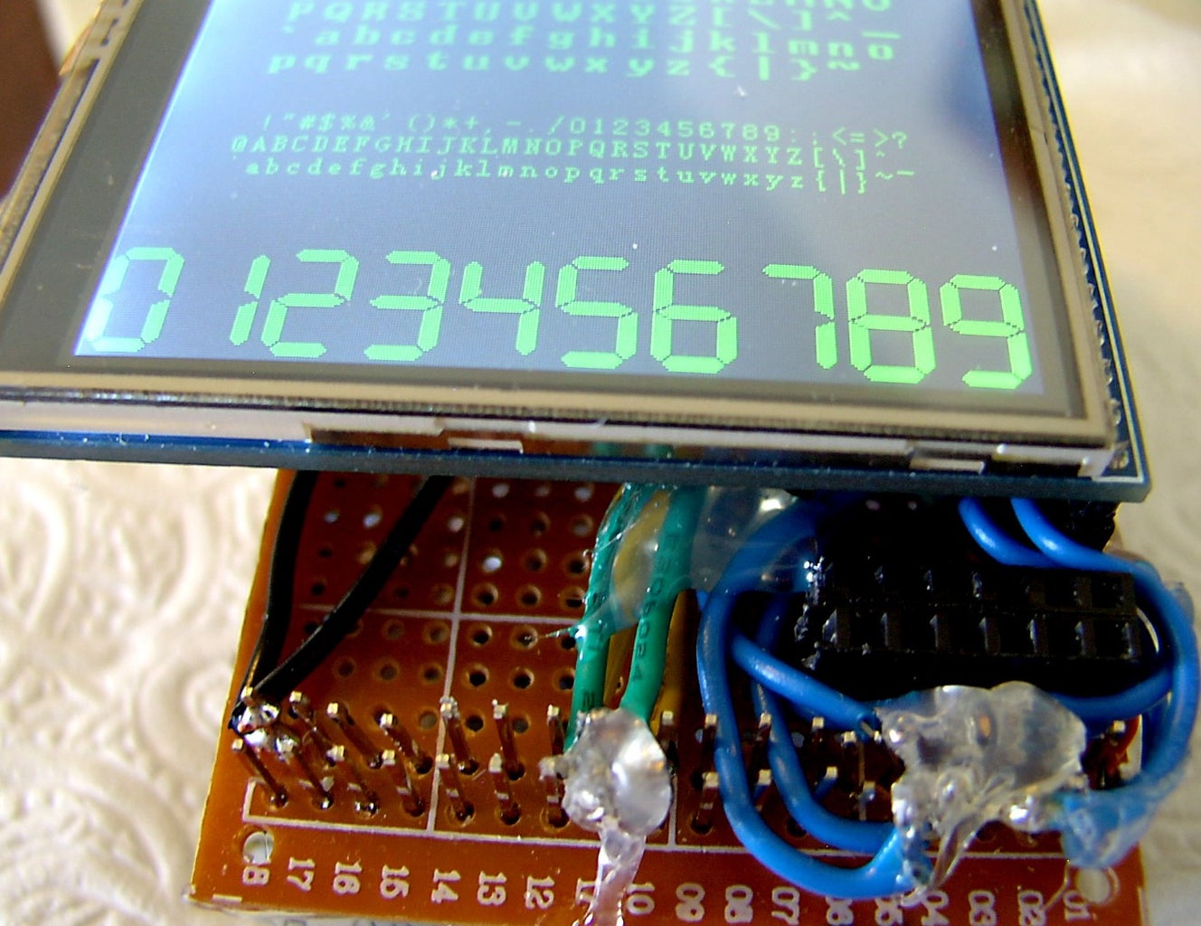
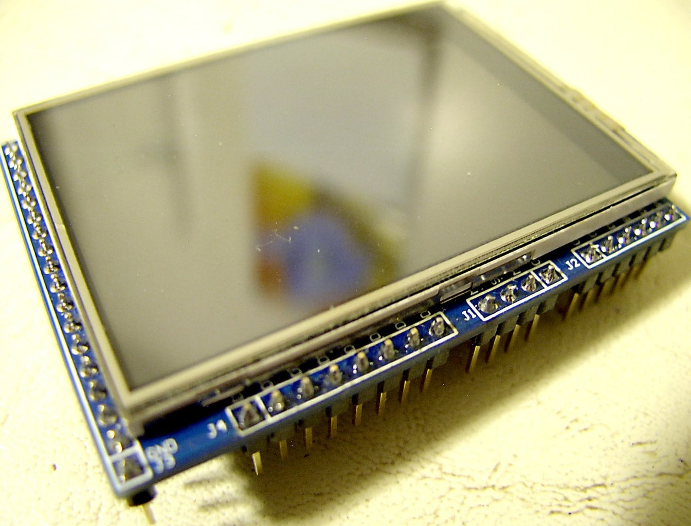
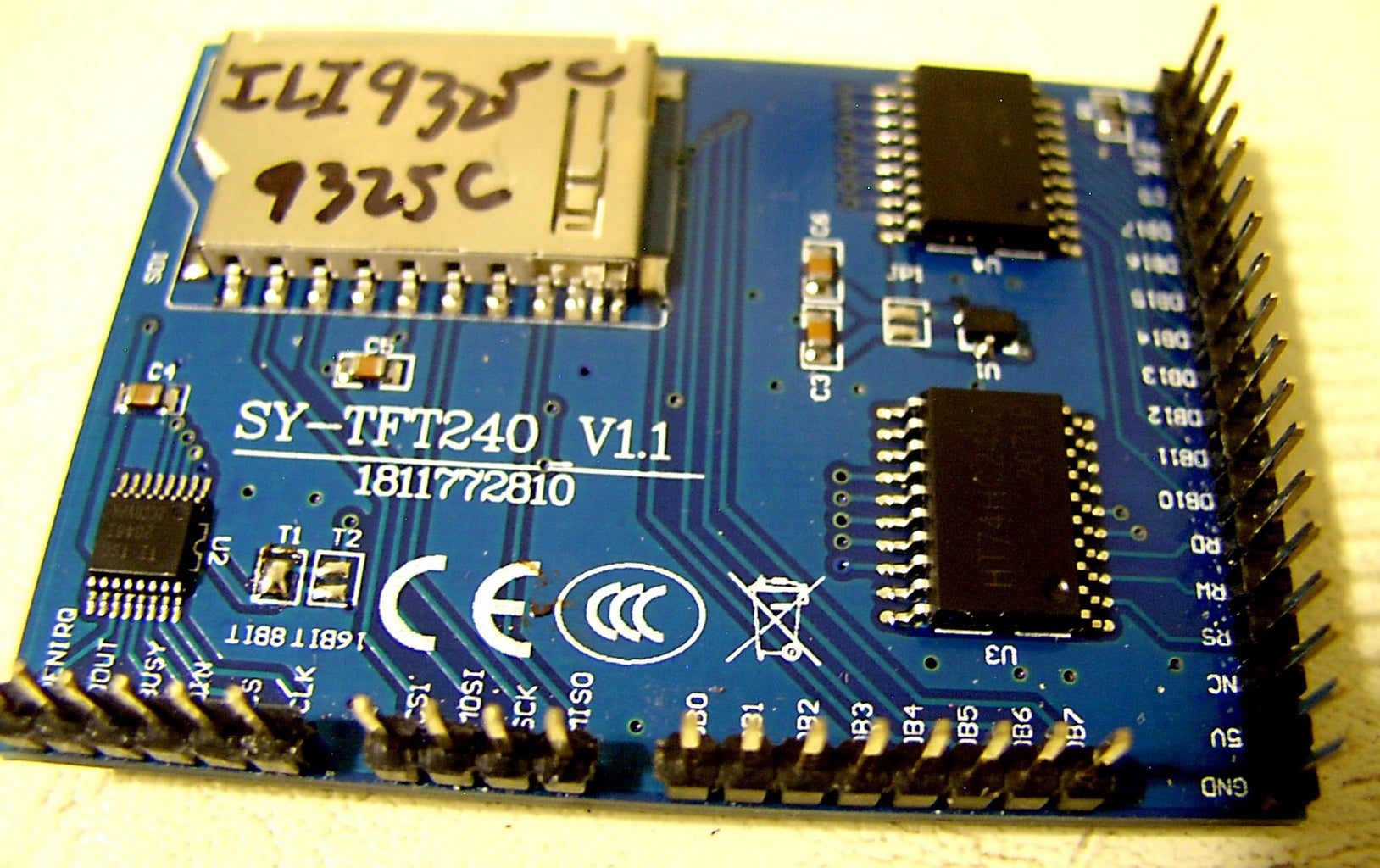
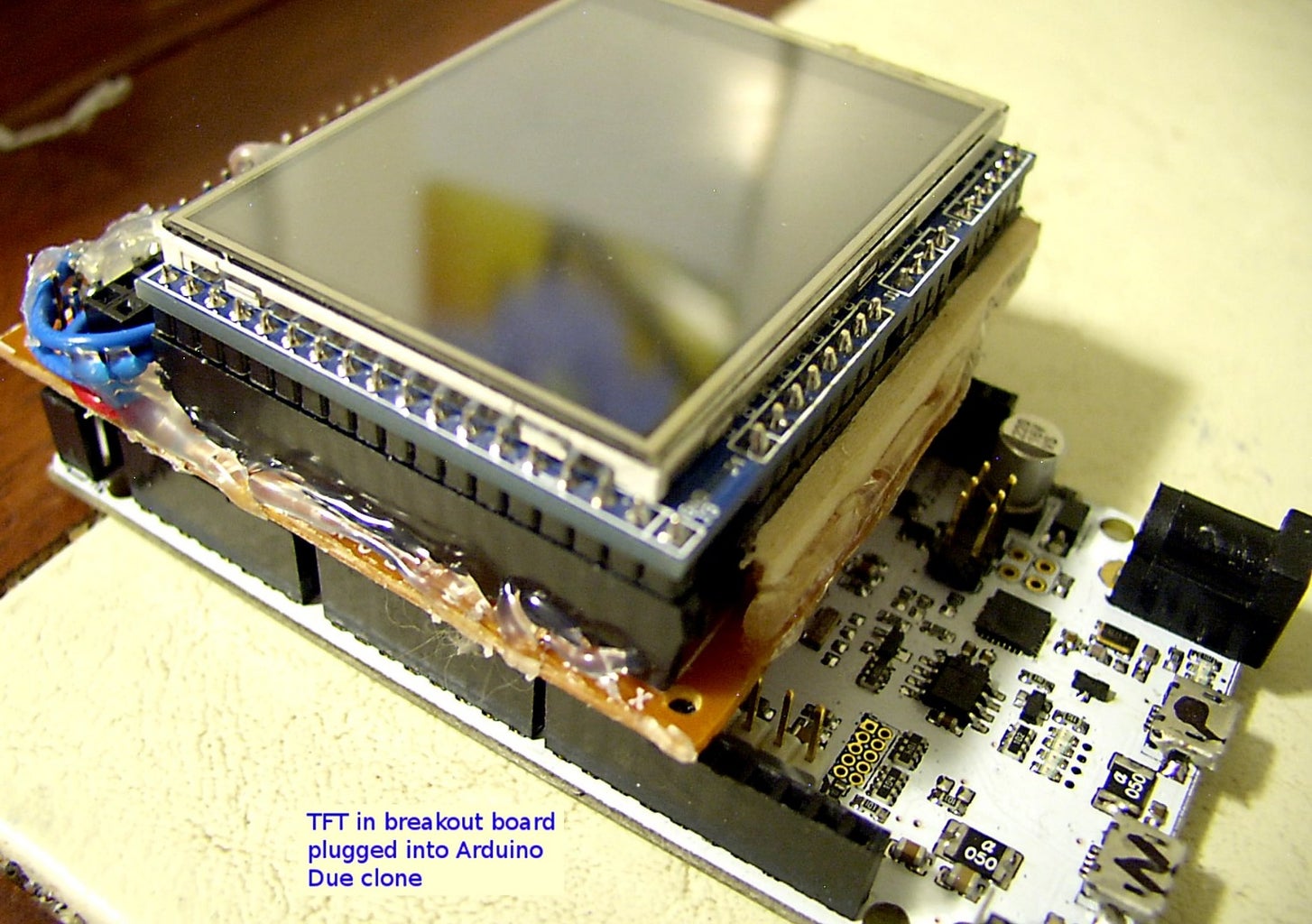
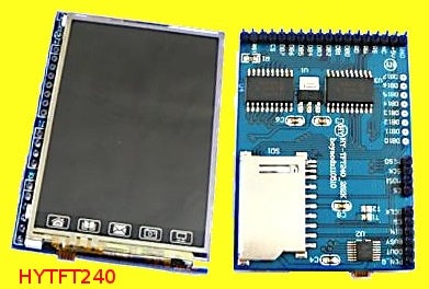
This one is a bit of an oddball. It's a clone of the more common HY-TFT240, and it has two rows of pins, set at right angles to one another. To enable the display in 8-bit mode, only the row of pins along the narrow edge is used. The other row is for the SD card socket on the back, and for 16-bit mode. To interface with an Arduino ( Mega or Due), it uses Henning Karlsen's UTFT library, and the driver is ILI9325C. Its resolution is 320x240 (hires!) and it incorporates both a touch screen and an SD card slot.
Buy it here.
http://www.ebay.com/itm/141197618099
At $7.50 + $1.19 postage, this is the most expensive of the displays discussed here, because of the high resolution and the touch screen.
Hardware connections:
The TFT uses the 18-pin connector (J3) along the short side of the display.
Display  1    2    3    4    5    6    7     8     9
         Gnd  Vcc  N/C  RS   RW   RD   DB10  DB11  DB12
Arduino  Gnd  Vcc       D38  D39  Vcc  D22   D23   D24
Display 10 11 12 13 14 15 16 17 18
DB13 DB14 DB15 DB16 DB17 CS N/C RST N/C
Arduino D25 D26 D27 D28 D29 D40 D41Notes:
- N/C = not connected.
- Vcc = 3.3v
- In 8-bit mode, only the high-order bits of the parallel data buss are used.
The UTFT library:
http://www.rinkydinkelectronics.com/library.php?id=51
Attachments
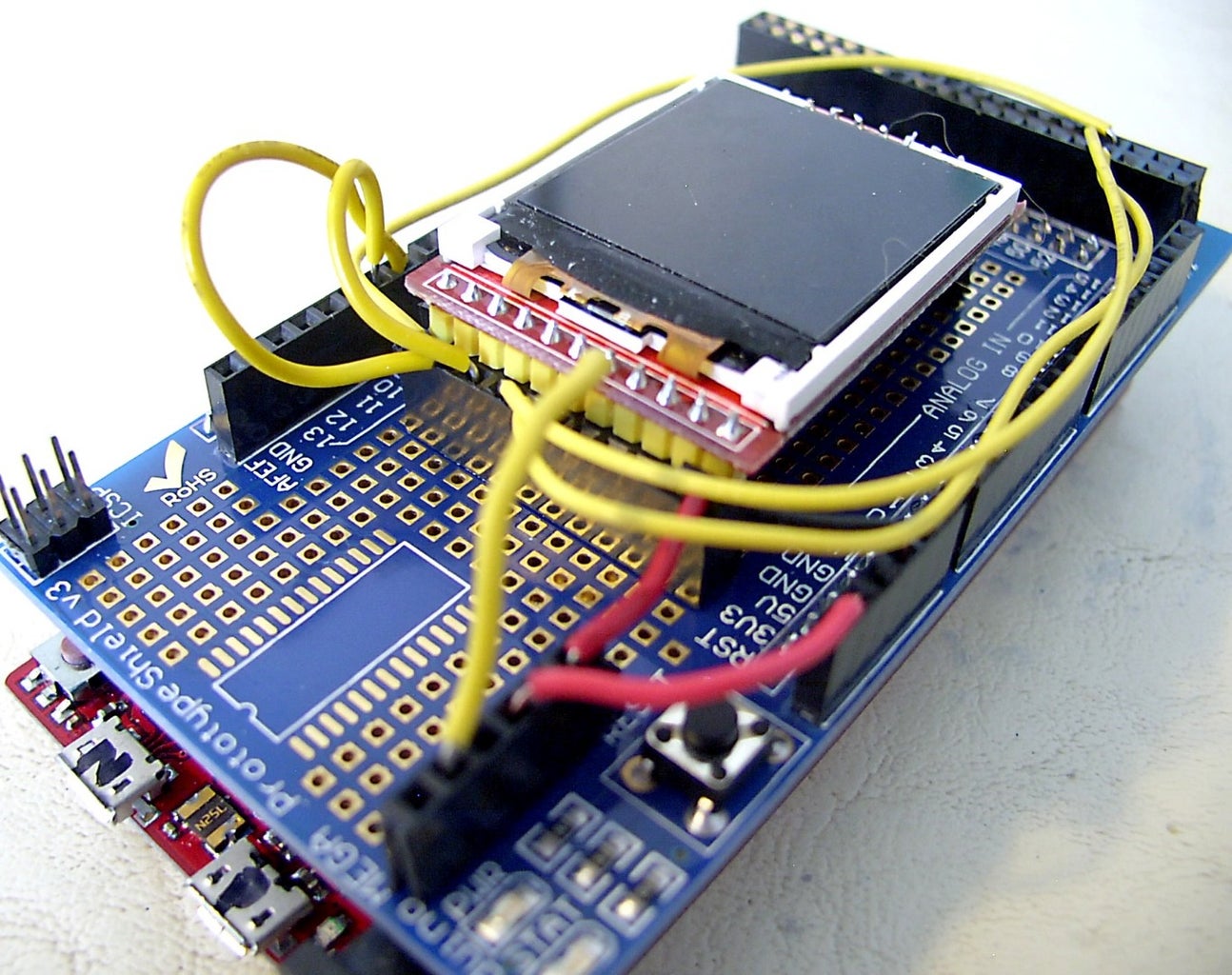
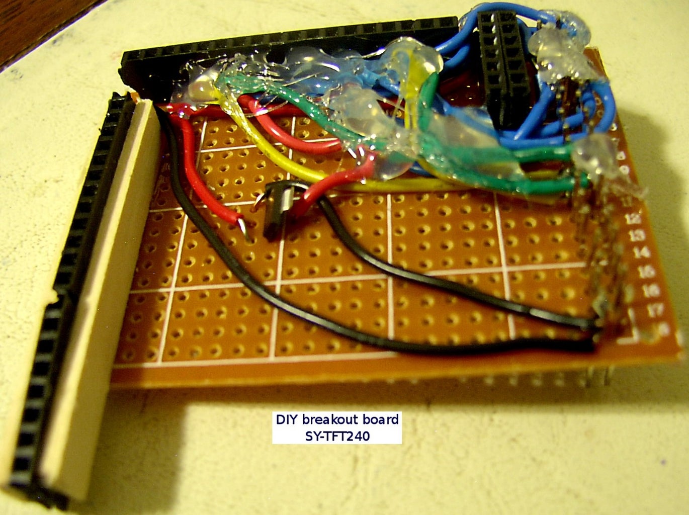
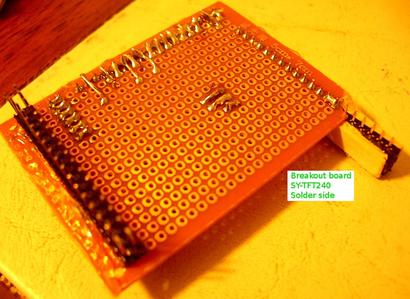
Step 7: Building Breakout Boards and "shields"
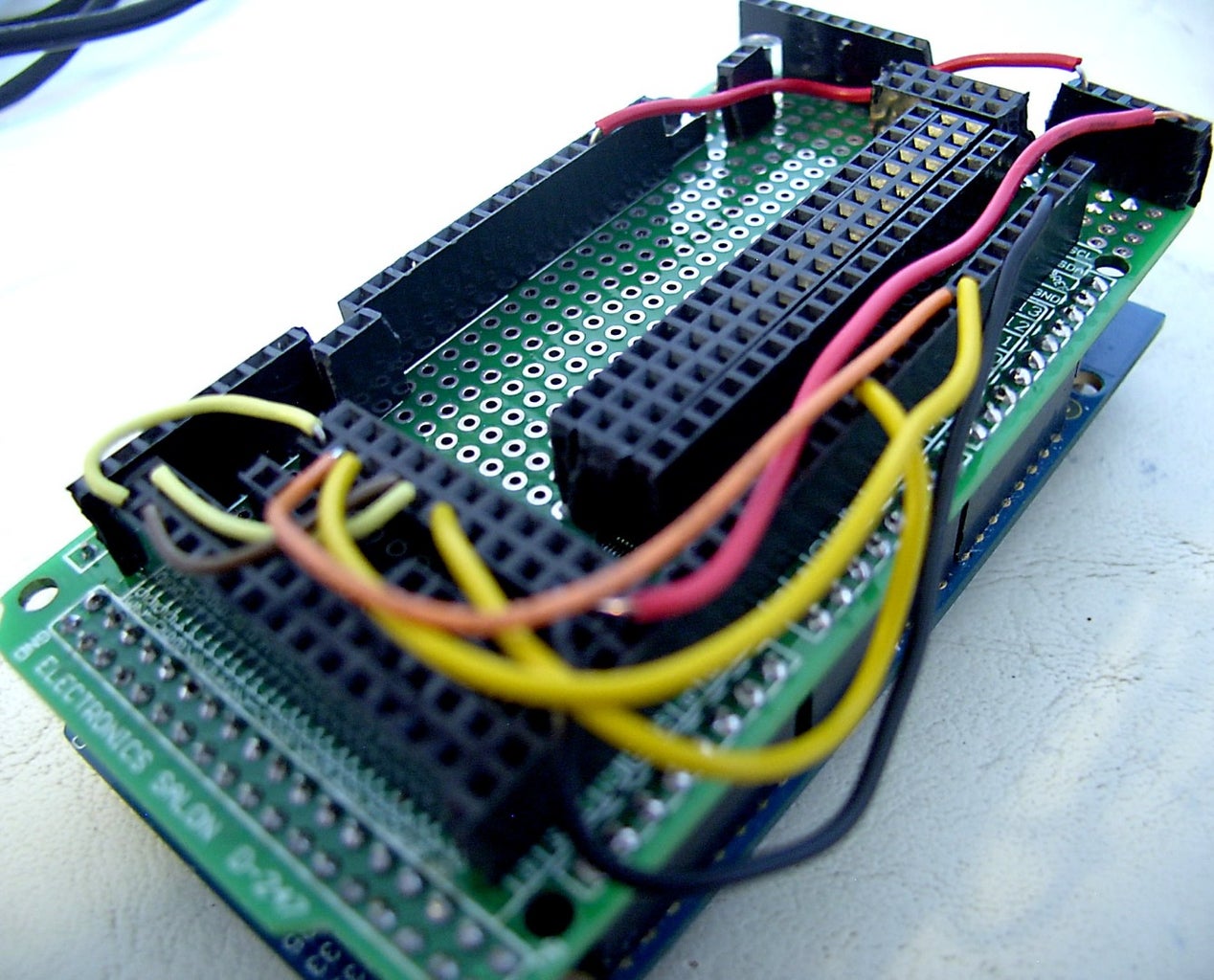

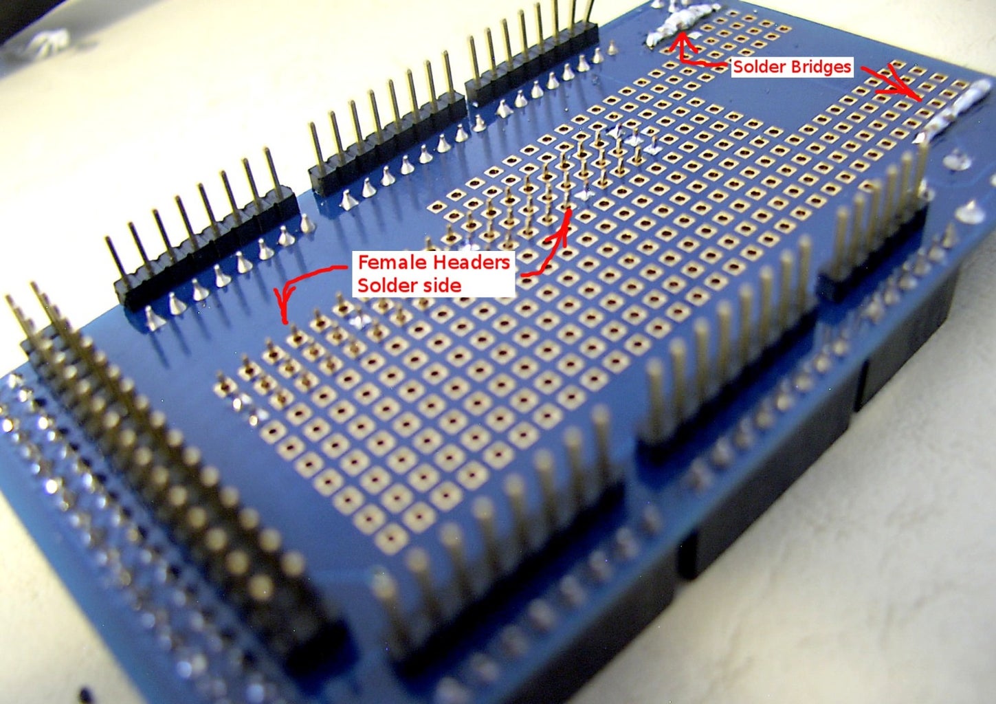

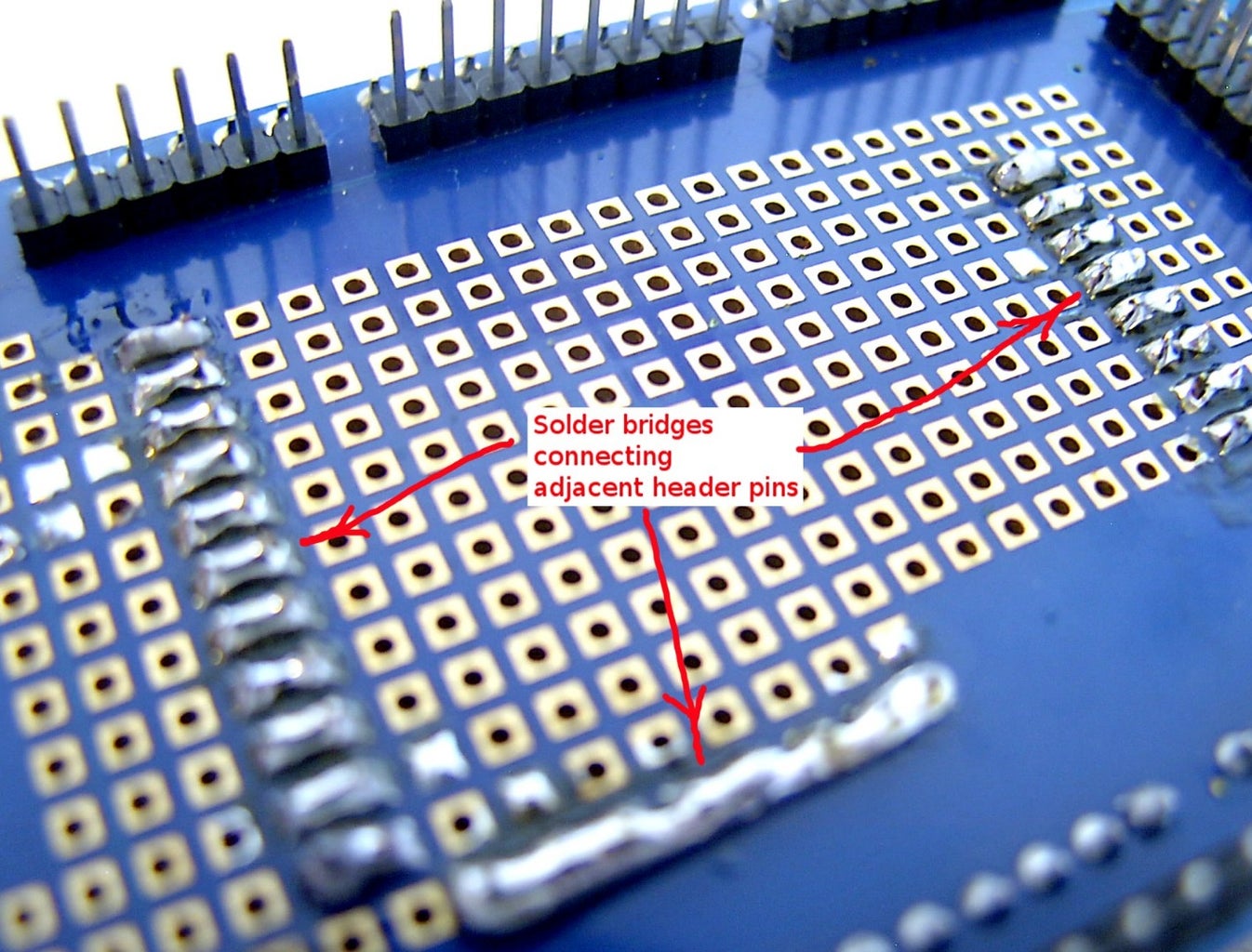
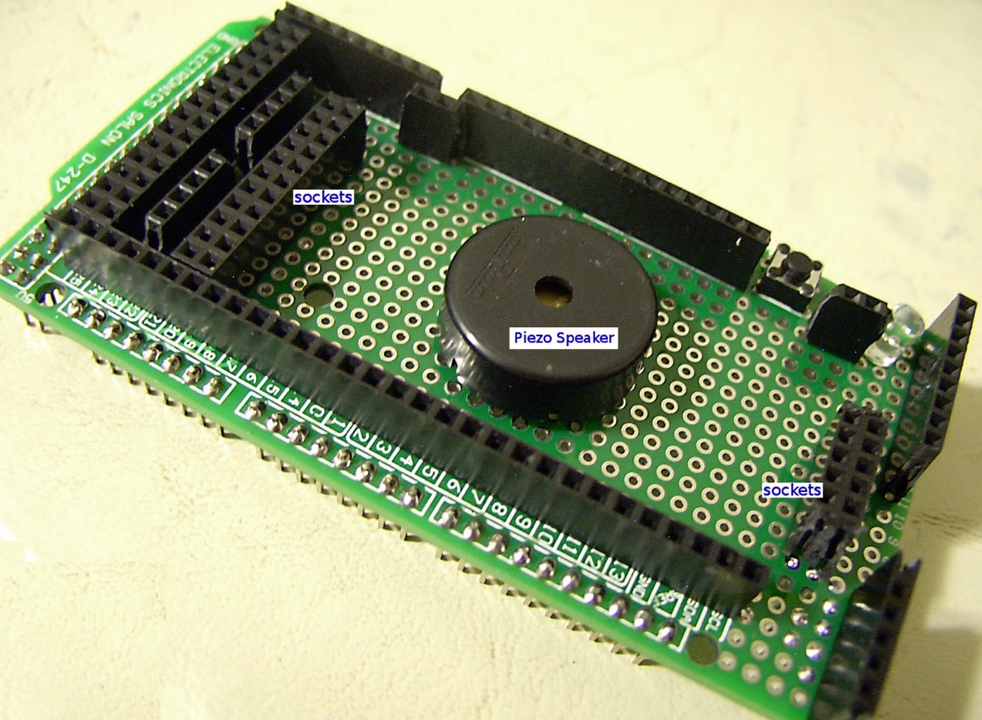

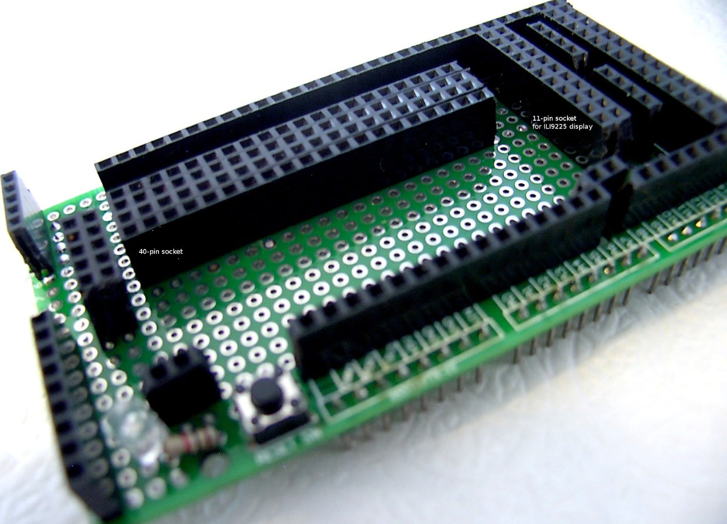
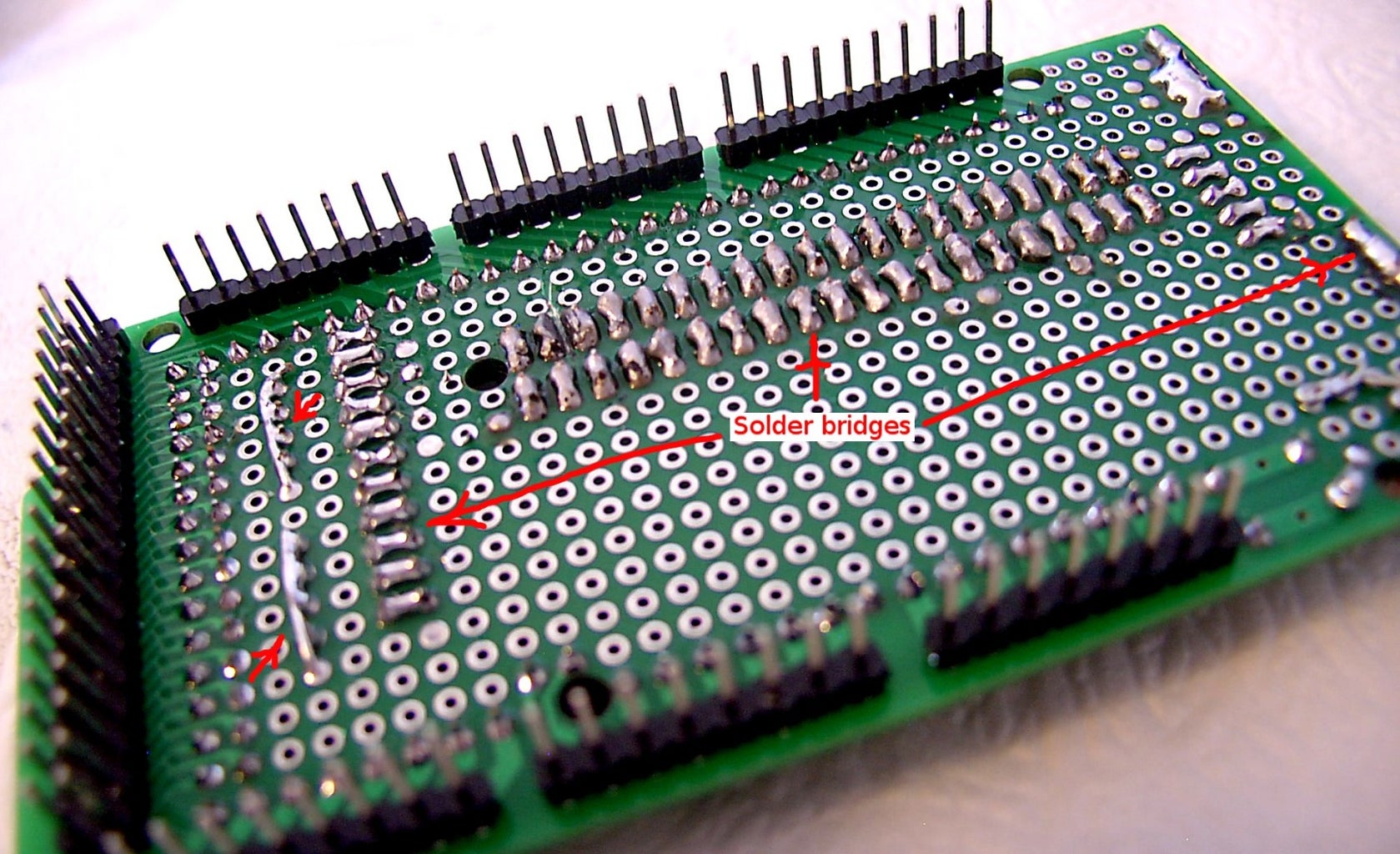
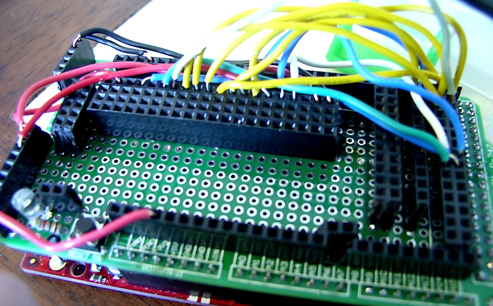

Having determined that a particular TFT display will work with the Arduino, it's time to think about a more permanent solution -- constructing hard-wired and soldered plug-in boards. To make things easier, start with a blank protoshield as a base, and add sockets for the TFT displays to plug into. Each socket row will have a corresponding row next to it, with each individual hole "twinned" to the adjacent hole in the adjoining row by solder bridges, making them accessible to jumpers to connect to appropriate Arduino pins. An alternative is hard-wiring the socket pins to the Arduino pins, which is neater but limits the versatility of the board.
Note that the sockets are made from 0.1" female header strips.
The key to an effective DIY shield is a neat and logical layout. Sketching the prospective shield on quadrille (graph) paper may be helpful. A multitester or continuity tester might be useful for detecting wiring and soldering errors.
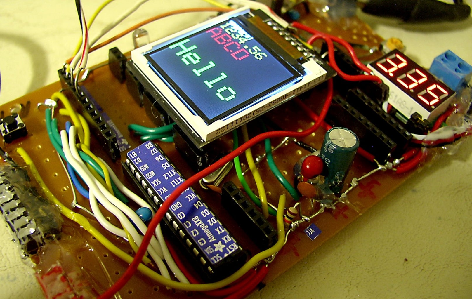
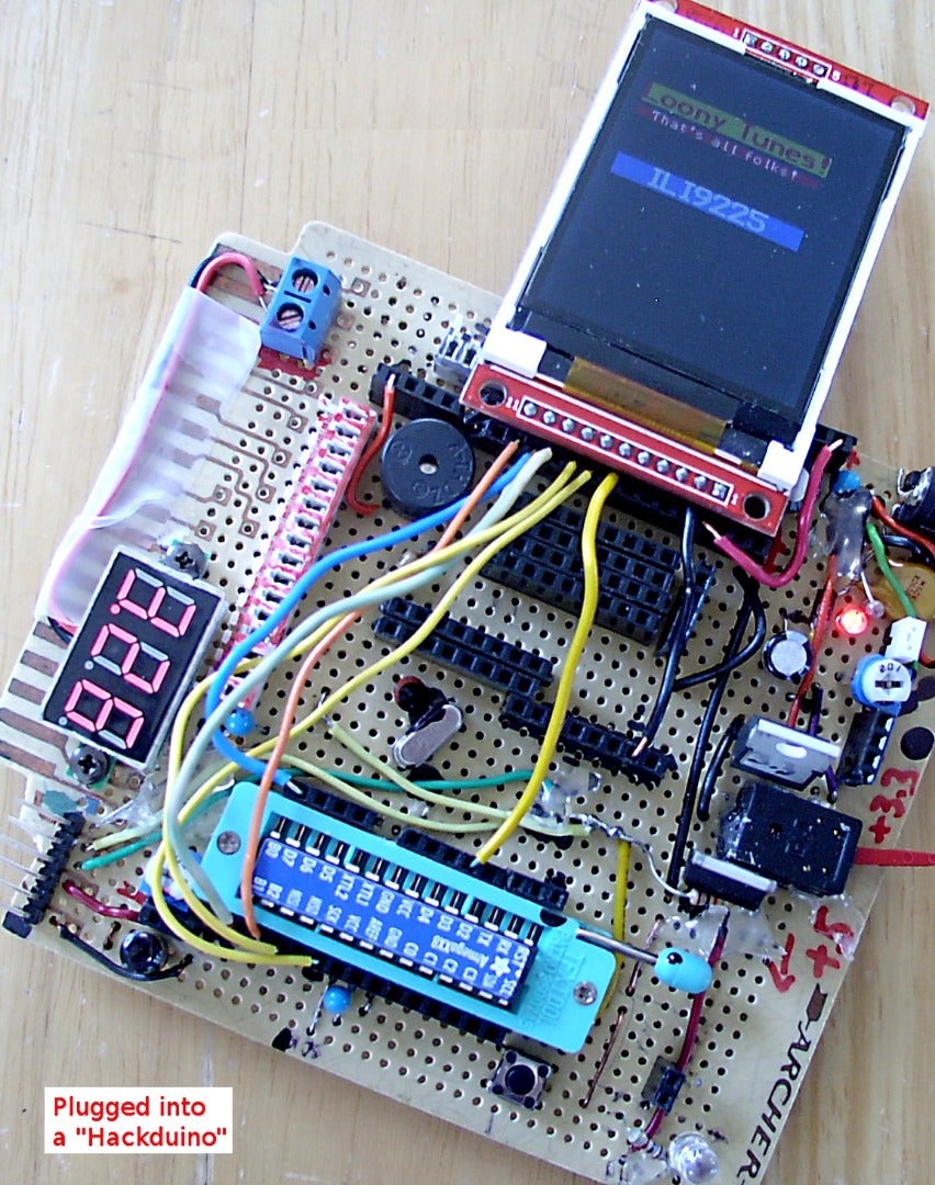
Step 8: A Practical Application
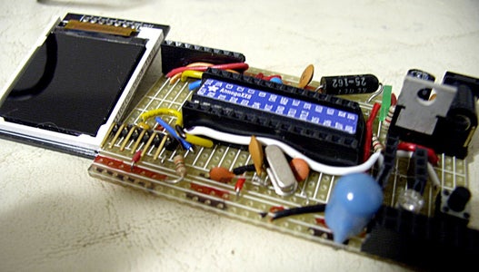
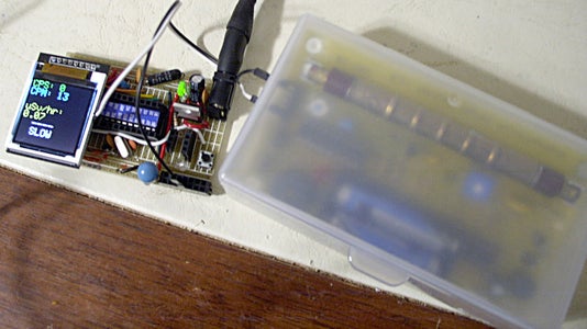
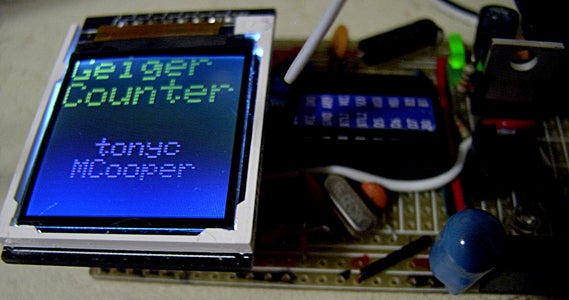

Here is an ILI9163C 128x128 pixel LCD display socketed in a mini hackduino board.
With the appropriate sketch loaded into the ATM328, it acts as a dedicated display for the Mighty Ohm geiger counter.
Attachments
Step 9: Summary

What we have learned:
- That an Arduino can drive many commonly available cheap TFT LCD displays.
- That we need to identify the display family and the library containing the necessary drivers.
- That we need to figure out the hardware wiring -- which display pins go to which Arduino pins.
- That it's possible to hack together breakout boards or shields, to modularize and simplify reuse of the displays.
- That some displays need an Arduino Mega or Due because of library memory requirements.
Driver      Resolution     Uno Mega Due
             (pixels)
---------------------------------------
ILI9163C    128 x 128       X
ITDB18SP    128 x 128       X*  X    X
ILI9225     220 x 176       X   X    X**
S6D0164     220 x 176           X    X
ILI9325C    320 x 240           X    X
* Works on Uno in text mode only.
** Should work, but needs tweaking.
Step 10: A TODO List

"Ever tried. Ever failed. No matter. Try Again. Fail again. Fail better."
  -- Samuel Beckett
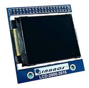
- Figure out how to interface other TFT displays, such as the Ihhaos LCD-2000 series.
- Experiment with using the onboard SD card slot to load pictures and fonts onto the LCD display.
- Figure out how to enable the touch screen on those displays that have one.
- Interface working displays with other projects. [Done! See Step 8]
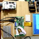
- Interface TFT LCD displays of the types discussed with a Raspberry Pi and Beaglebone Black.
- Build complex projects, such as a portable oscilloscope, with a TFT LCD display.
These would be nice topics for future Instructables.


