

Introduction: Using an In-System Programmer


We are familiar with the Arduino IDE as a means of uploading sketches. But, there are limits to the IDE. If we are developing complex applications for the ATMega328, then the IDE does not suffice. If there are multiple source files that compile to a hex output for flash memory and another for eeprom, then the IDE falls short. In either case, we need an ISP, an in-system programmer that connects directly to the ICSP headers on the Arduino board, and software to upload the hex file(s) to the ATM328.
I ran into this when I purchased a "Transistor Tester" from an on-line vendor. This is a Chinese clone of a device developed by Markus Frejek and Karl-Heinz Kübbeler. Based on an ATMega328, it measures resistance and capacitance, and identifies diodes and transistors, among other things. For about $12.50 (delivered!) this nifty gadget is a useful addition to a tinkerer's toolbox. But, it has one problem. If you, by mistake, try to measure an electrolytic capacitor with a charge on it, you might blow up the ATM328 chip. No big deal, you think. You could always substitute another, for a couple of bucks, and program it to perform like the original. After all, you can always upload Markus Frejek's source code to a blank ATM328. But, could you really? Not with the Arduino IDE, you couldn't. It involves building a multi-file source code project, using a Makefile. Moreover, there are two object code files that result -- the hex file to upload to the 328's flash memory, and yet another hex file for the eeprom memory. The net result is that you need an ISP programmer. Fortunately these are fairly cheap. Unfortunately, they are not so easy to use.
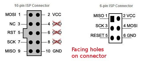
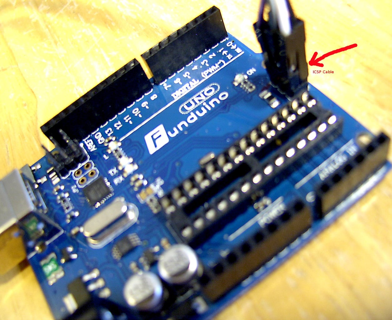
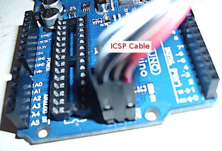
A standard Arduino board has a 6-pin ICSP header right next to the ATM328 chip. A cheap, Chinese clone AVR ISP Mk II programmer comes with a 10-pin cable. This is a problem, because you need a 10-pin to 6-pin coverter to connect to the ICSP header on the Arduino. Such converters are cheap, as little as a dollar or two on eBay, including delivery from China. But, it's also possible to make your own converter, using a set of 6 male-to-female jumpers.
Step 1: Parts Needed


- Arduino board, Duemilanove or Uno [clones will work]
- ISP programmer, preferably a cheap AVR ISP mk II [approx. $12 - $15 on eBay]
- 10-pin to 6-pin cable adapter, or a set of 6 female-to-male (Dupont) jumpers [ $1 - $5 on eBay]
- ESR "Transistor tester" or equivalent, available on eBay and elsewhere
- A couple of ATM328 chips, blank or programmed [$2.50 - $3.00 each on eBay]
- Avrdude toolchain installed (if Arduino IDE has been installed, then this is already the case)
- Linux or UNIX operating system on your computer. You can use AVR Studio under MS Windows for roughly equivalent functionality, but that is not what this tutorial is about.
Total cost of materials can range from about $15 to $40, depending on what you already have on hand.
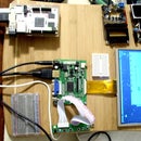
Step 2: Hooking Up the Hardware

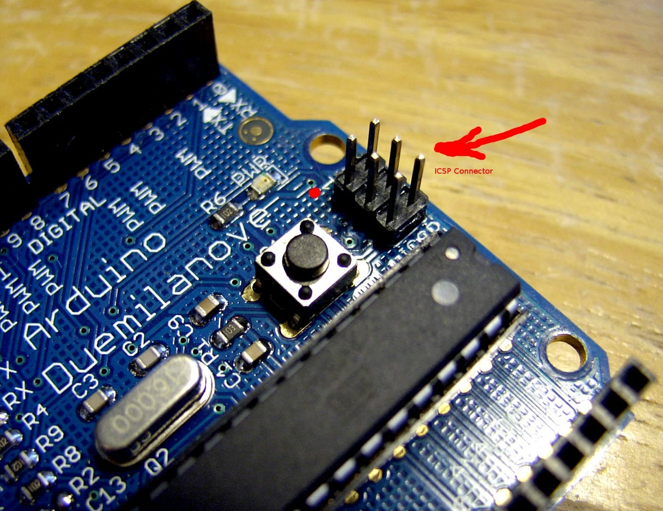


We will be using the ICSP (In-Circuit Serial Programming) header on a standard Arduino board to program the ATM328 chip. Sometimes referred to as the ISP (In-system Programming) header, it makes it possible to program chips "on the fly" without the need to remove them from the circuit.
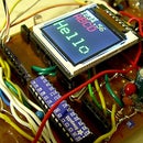
First, we will replace the ATM328 on our Arduino board with the target ATM328 that we will reprogram with the ISP programmer. Carefully extract the original '328 with an IC puller or lever it up and remove it with a miniature screwdriver. Then, insert the target '328 into the empty 28-pin socket on the board. Be sure to line up pin 1 of the chip with pin 1 of the IC socket.
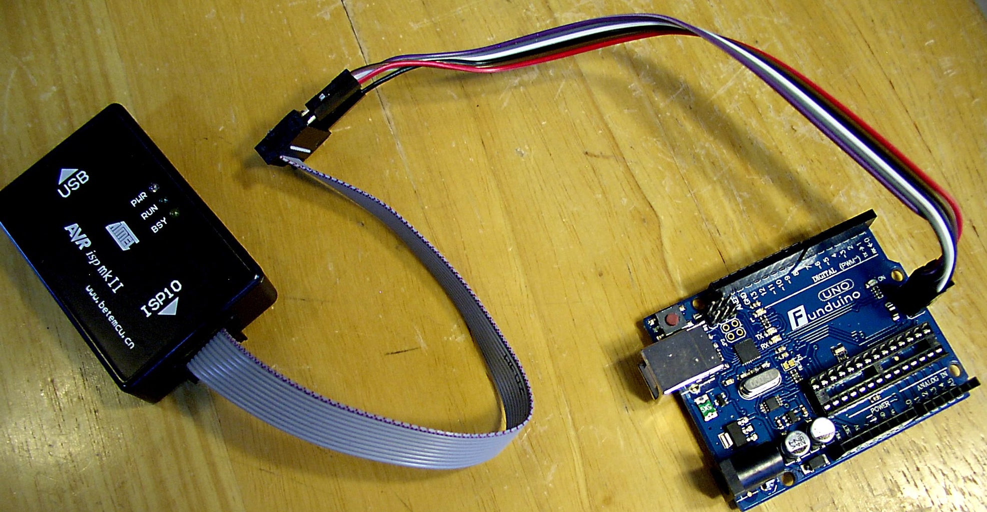
Now, we will hook the ISP programmer to the Arduino board's ISP header. Use either a 10-to-6-pin adapter or a makeshift adapter made from male-to-female jumpers. You will connect Vcc to Vcc, Ground to Ground, MOSI to MOSI, MISO to MISO, RST (reset) to RST, and SCK to SCK. See the pictures and diagram.
Finally, we hook the A-to-A USB cable from the ISP programmer to the computer's USB port. The PWR and RUN LEDs on the programmer light up. Note that the Arduino board does not get hooked to the computer or to a power supply. The ISP programmer pulls power from the computer USB port and supplies it to the Arduino board.
Once more:
- The ISP programmer connects to the computer USB port with the A-to-A USB cable.
- The ISP programmer connects to the ICSP header on the Arduino board with the 10-pin cable and a 10-to-6-pin adapter of some sort.
- The target ATM328 chip inserts into the 28-pin IC socket on the Arduino board.
- The Arduino board itself does not connect to the computer (with a USB cable), nor does it connect to a power supply.
Step 3: Getting and Compiling the Firmware


We now know how to hook up the ISP programmer. Let us proceed, then, to get the source code for the firmware for the Transistor Tester.
http://www.mikrocontroller.net/svnbrowser/transist...
And here is the documentation. In German. http://www.mikrocontroller.net/articles/AVR_Trans...
If you should need a downloadable copy of the original firmware: http://www.mediafire.com/download/ds955tag3zawl4t...
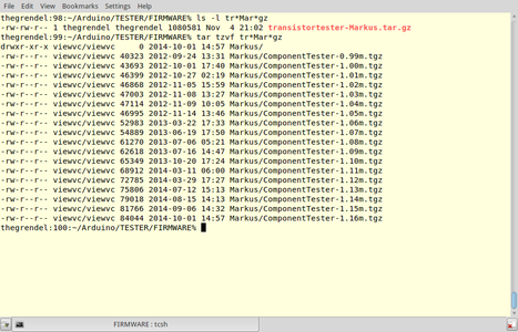
Okay, you have downloaded tar.gz archive files. These are sometimes called "tarballs," and the command to unarchive/unpack them is tar xzvf filename.tar.gz. So, we will type tar xzvr transistortester-Markus.tar.gz in an xterm window. Oh, yes, by now you have probably figured out that you should be running Linux or some UNIX variant in order to be able to do this.
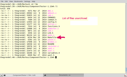
In this particular instance, the tar.gz tarball unarchives into a set of other tarballs. We choose one of these,
ComponentTester-1.13m.tgz and, in turn, unarchive that one: tar xzvf ComponentTester-1.13m.tgz.
Lots of files there. Now, what to do with them? There is a Makefile among these unarchived files that controls the compilation or build. From the command line, type make.
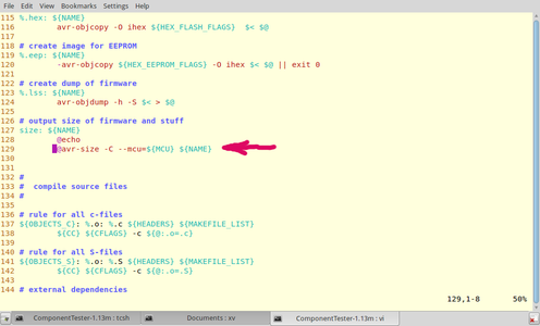
What's this? We get a compilation error!
avr-size: invalid option -- 'C'
What's going on? Don't worry, it's no big deal. Lines in the Makefile preceded by a @ are external commands. These are not essential to the compilation process, so we can just comment them out with a # at the beginning of the offending line. Now, run make again. That's better -- no errors.
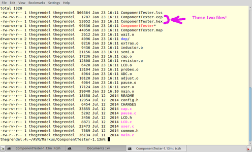
The compilation process produces quite a number of output files, but the only ones you need are the eep and hex files: ComponentTester.eep and ComponentTester.hex -- these are the ones you will upload to the ATM328 chip. The ComponentTester.hex file will go into flash memory, while the ComponentTester.eep file is for the eeprom memory.
Step 4: Programming the ATM328 Chip


We now have the two hex files to write to the 328's flash and eeprom memories.
First, hook up the hardware, as discussed in a previous step. We will invoke avrdude from the command line, as root, to upload the files to the chip.
# As root:
To write ComponentTester.hex to ATM328 flash memory
avrdude -p m328p -P usb -c avrispmkII -U flash:w:ComponentTester.hex:i -v
To write ComponentTester.eep to ATM328 eeprom memory
avrdude -p m328p -P usb -c avrispmkII -U eeprom:w:ComponentTester.eep -v
[Consult the avrdude documentation for the meaning of the various flags.
Most of them are self-evident.]
Pay attention to the messages that avrdude emits (see pics).
verifying ...
... verified
avrdude done. Thank you.
This tells you that the write to memory was successful.
Note that -v is the verbose flag. You get lots of information about what is going on.
IMPORTANT: Burn flash memory first, then eeprom!
The reason for this is that the flash memory write cycle erases eeprom memory.
Congratulations! You successfully reprogrammed an ATM328 chip.
Step 5: Onward and Upward

Well, it has been quite an adventure. Along the way we got a brief introduction to avrdude and a mini-tutorial on using an ISP programmer.
An advantage of using avrdude is being able to use Standard C or C++, rather than the stripped-down Arduino IDE version. An advantage of using an ISP programmer is that we have much more flexibility than the Arduino IDE gives us, and we can program members of family of AVR chips other than the ATM328, such as the ATtiny85 and the ATmega644P. Now, we can get serious about learning the intricacies of embedded system programming.


