

Introduction: 1.3-15V Analog Power Supply


This power supply has an output of variable voltage from 1.3 to 15 Volt because it's based on an LM317 regulator in order to obtaining those voltages while a 0-15V Analog Monitor shows those ranges of reading with help of a potentiometer. Go to: http://www.youtube.com/watch?v=nWfUacvEBIw
What you will need:
Soldering iron and solder
Helping Hands
Needle nose pliers
Wire cutters/strippers
Wire #22
Multimeter
Electrical Drill
Drill Bits: 1.5", 3/8", 5/16"
Krazy glue
Step 1: Bill of Materials


1 ABS Plastic Box about 7"x 5" x 3"
1 Analog Voltage Power Meter 0-15V
1 Resistor 1.5 K Ohm, 1/4 Watt
1 Connector BNC Receptable
1 23" Alligerator Clip to BNC Cable, Type Cable Black
1 Potentiometer 10K Ohm with switch
1 Knob 1/4" with Screw
1 Standard Regulator 1.2 Volt to 37 Volt, 1.5 Amp
1 TO-220 heatsink with 1 Hole
1 AC/DC Unregulated Wall Transformer 9V, 0.6A ( For obtaining about 16.3 Volt)
1 PCB 2" x 2"
1 Capacitor Radial 1uF, 25V
1 Ceramic Disc Capacitor 0.1uF, 25V
1 Resistor 220 Ohm, 1/4 Watt
1 Power Jack Connector Male
Step 2: Preparing Your ABS Plastic Enclosure


In the front side of your enclosure, you need to drill 3 holes so that you can install the Analog Voltage Power Meter, the BNC connector, and the potentiometer with switch. Those holes should from left to the right: 1.5", 3/8", 5/16" respectively.
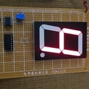
Step 3: Preparing Your Analog Voltage Power Meter


Observe the back side of your Analog Voltage Power Meter and connect the resistor of 1.5K Ohm to its positive terminal.
Step 4: Preparing Your BNC Connector


In this step, it's important that the positive and negative terminal be identified so that you can connect correctly this device. Also, should remember that this BNC connector has center positive, in this case, you will take like positive terminal the central terminal of this component.
Step 5: Preparing the Potentiometer and Its Switch


Take the potentiometer of 10K Ohm , by seeing it in its front side, and connect together its two first terminals from left to the right. Those two terminals will be connected to the negative terminal of your power supply while the other terminal will be joined to the "adj terminal" (1) of your voltage regulator (LM317). In the back side of your potentiometer, you can observe the switch of your power supply.
Step 6: Installing the BNC Connector


Install the BNC connector in the central hole done previously in your enclosure.
Step 7: Installing the Analog Voltage Power Meter


Install the Analog Voltage Power Meter in the first hole done previously in your enclosure by utilizing Krazy glue only if you want. or drill a hole for inserting the screws of your Panel Meter.
Step 8: Installing the Potentiometer With Swith and Its Knob


In the last hole done previously in your enclosure, install the potentiometer with switch and its knob.
Step 9: Preparing the Power Jack Connector


Take the bottom terminals of your power jack connector like negative terminals while the back terminal like positive terminal because you should remember that this type of connector is center positive.
Step 10: Analog Power Supply's Diagram

Observe carefully your diagram so that you can assemble correctly the project because each component of this kit is critical that they be connected exactly as they appear in the project's diagram.
Step 11: Installing the Power Jack Connector


Take the part of the back side of your enclosure and drill a hole of 5/16" so that you can install the power jack by using Krazy glue. Once you install the component will look like in the photo 2 of this step of your project.
Step 12: Complete Your PCB


Complete your PCB by mounting the components on it. That is, install the LM317 voltage regulator, the resistor of 220 Ohm, the capacitor of 0.1uF, the capacitor of 1uF, and the heatsink without forgetting thet the project's diagram should be respected for finishing successfully this project.
Step 13: Install the PCB Done Inside Your Enclosure


Install the PCB done inside your enclosure, and connect to set together all components by remembering that it's necessary that the project's diagram be followed step by step for success in this project.
Step 14: Close Your Enclosure


Take the back side part of your enclosure that is the lid so that you can close the box. This lid is also the part where you put previously the power jack connector, and it should be connected with the rest of the circuit before closing the box.
Step 15: Plug the Unregulated Wall Transformer Into the Power Jack Connector

Plug the unregulated wall transformer into the power jack connector so that you can use this project.
Step 16: Complete Your Project


Plug the BNC cable into the BNC connector so that you can complete your project.


