

Introduction: Arduino & Android Based Bluetooth Controll Password Protected Smart Door Lock (Save Your Home)


We everybody are concerned about the security of our home. World becoming smarter and smarter everyday and we want to control and secured our thing in smarter way. In this tutorial I will explain how to made a arduino based DIY smart lock which can be open and closed using password sent from android smartphone by using Bluetooth.
This smart Lock is the secure, simple, and easy to manage your home’s lock. This lock needs no keys and the lock is attached inside the door and you can control it from outside the door. As the lock is inside the door there is no way to break the door by thief.
You can find some smartphone control lock which required to replace you entire lock system but in my tutorial I will made the thing using your traditional old lock.
This project is based on the android application, android application send password through Bluetooth. An android application is required to open and close the lock and I will explain the details of android app development in the later part of the tutorial. If password is matched to your preset-lock password then lock will be open and sent a feedback to your phone.
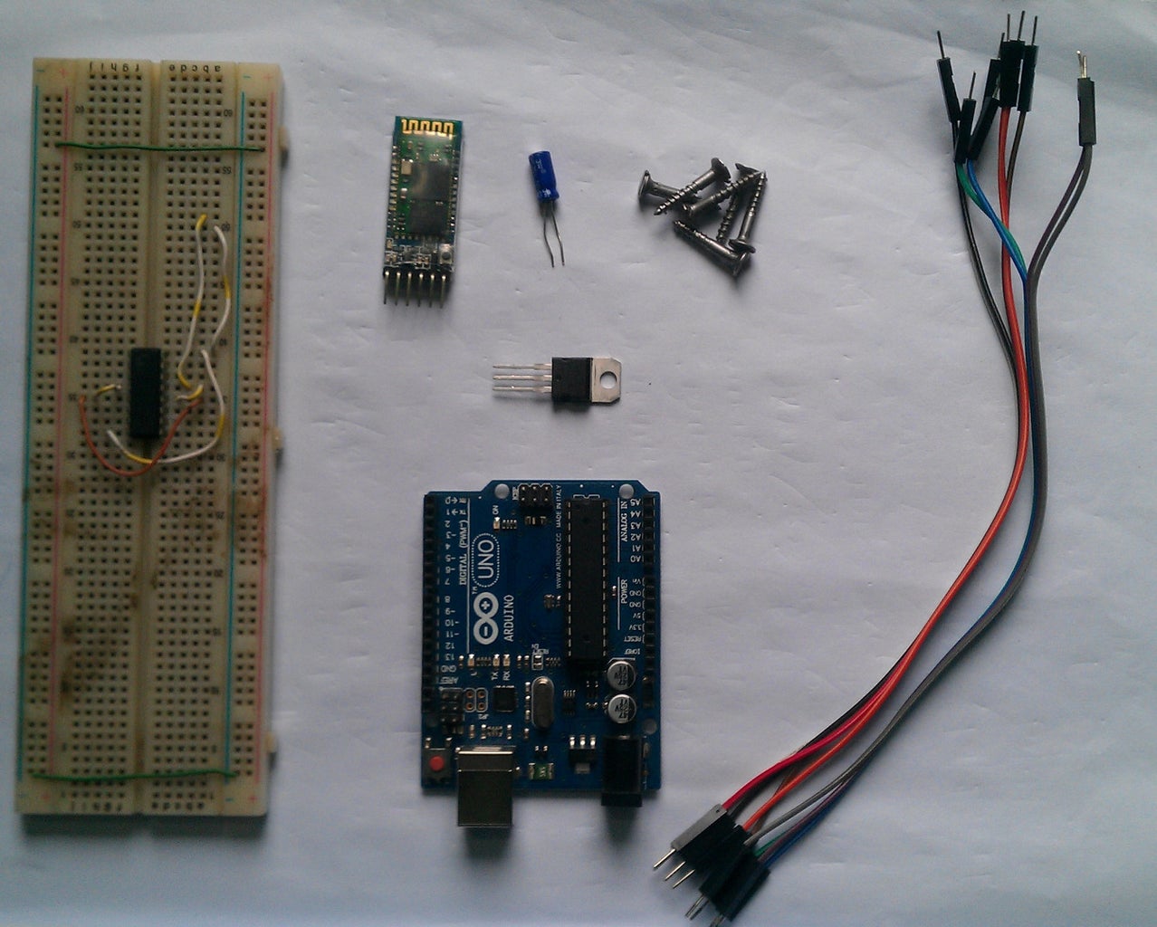
Step 1: Required Components for Arduino Bluetooth Control Door Lock


| 1. | Arduino Uno | 1pc |
| 2. | Bluetooth module (HC-05) | 1pc |
| 3. | Laser Movementing tray from old CD/DVD ROM | 1pc |
| 4. | Motor Driver IC (L293D) | 1pc |
| 5. | Voltage Regulator (LM7805) | 1pc |
| 6. | Electrolytic Capacitor (0.33uF) | 1pc |
| 7. | Electrolytic Capacitor (1uF) | 1pc |
| 8. | Door Lock | 1pc |
| 9. | Breadboard | 1pc |
| 7. | Android Smartphone | 1pc |
| 10. | Screw (optional) | 6pcs |
| 11. | Jumper Wires |
Step 2: Components Details for Smart Door Lock


Arduino Uno: Arduino Uno is the most popular development board in Arduino family. It is not mandatory to use arduino uno, you can use another member from the arduino family such as arduino nano or arduino micro. You can also use standalone atmega328p without using arduino baord. A well explain tutorial "From Arduino to a Microcontroller on a Breadboard" for standalone atmega microcontroller is here.
Bluetooth Module (HC-05): Bluetooth is a type of wireless communication used to transmit voice and data at high speeds using radio waves. It’s widely used in mobile phones for making calls, headset and share data. This type of communication is a cheap and easy way to control something remotely using arduino. For communication with arduino using blutooth a bluetooth module need to be connected with arduino. Several model of bluetooth module are available. I am using here HC-05 a very common and cheap one. HC-05 module has 6 pins. We have to connect 4 pins to arduino, they are:
RXD
TXD
VCC
GND
RXD will receive data from arduino; TXD will send data to arduino; VCC is the power supply (3.3V to 6.6V) and GND is the ground. For details click here .
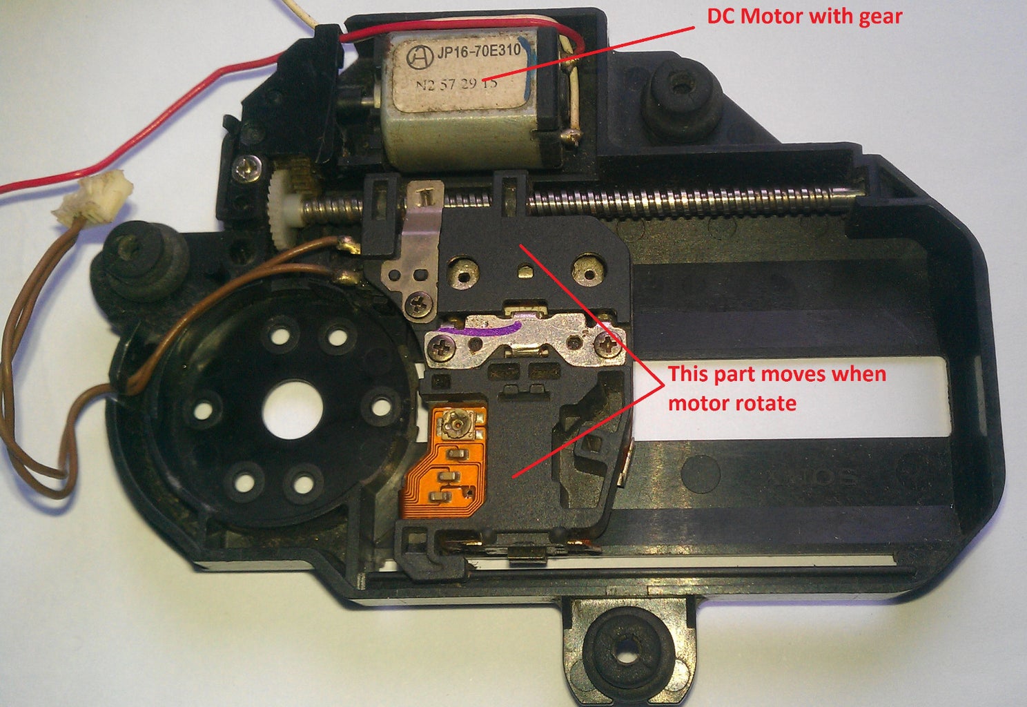
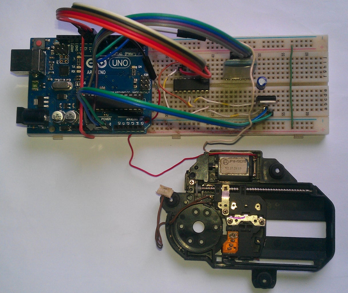
Leaser Movementing try: I don't know the actual name of the part. This is the part of CD/DVD player which move the leaser LED for reading the CD. This part contains Two DC motors. One for spinning CD and another for moving leaser diode. We do not need the CD spinning motor, you can remove it. You also can find this part fro old computer CD/DVD ROM. For disassembling this from a CD drive check the link: https://www.instructables.com/id/Disassembling-a-CD...
Motor Driver IC (L293D): L293D is a dual H-bridge motor driver integrated circuit (IC). Motor drivers act as current amplifiers since they take a low-current control signal and provide a higher-current signal. This higher current signal is used to drive the motors.
L293D contains two inbuilt H-bridge driver circuits. In its common mode of operation, two DC motors can be driven simultaneously, both in forward and reverse direction. The motor operations of two motors can be controlled by input logic at pins 2 & 7 and 10 & 15. Input logic 00 or 11 will stop the corresponding motor. Logic 01 and 10 will rotate it in clockwise and anticlockwise directions, respectively.
Enable pins 1 and 9 (corresponding to the two motors) must be high for motors to start operating. When an enable input is high, the associated driver gets enabled. As a result, the outputs become active and work in phase with their inputs. Similarly, when the enable input is low, that driver is disabled, and their outputs are off and in the high-impedance state. For details of L293D check the datasheet attached herewith or click here.
Voltage Regulator (LM7805): This is a 5 volt regulator. Output of AC adapter is given to input of the regulator. Output of the IC is regulated 5V. This output is given to L293D and microcontroller. Pinout and datasheet of the IC is attached.

Step 3: Tools and Supplies for Smartphone Control Door Security
| 1. | Screw Driver |
| 2. | Soldering Iron and Solder if you want to use PCB instead of breadboard |
| 3. | Hot Glue Gun |
| 4. | Access to a Computer |
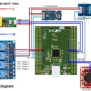
Step 4: Circuit Connection of Arduino and Android Control Door Lock
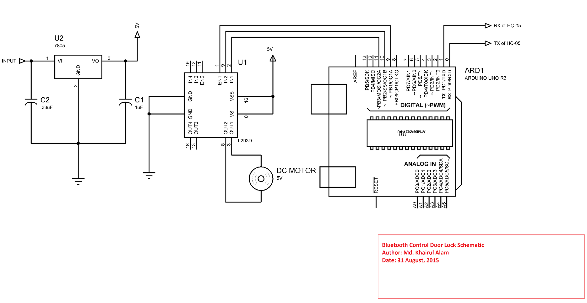


Circuit connection for our smart door lock is not so complex. Enable, IN1 and IN2 of motor driver IC is connected to the arduino 9, 10 and 11 pin. Out1 and Out2 of motor driver is connected to the DC motor of leaser movement mechanism. L293D has two input voltage, one for IC itself and another for motor voltage. I have connected 5V to both pin, our motor will run well in 5V. This driver has 4 ground pin, and all are connected to ground. Heat sink is not required here. A 5V regulator IC (LM7805) is used here and its input is connected to the output of an AC adapter. A 7.5V to 12V AC to DC adapter will work fine. The output of the adapter is directly connected to arduino VIN pin because arduino board has an internal voltage regulator.
TX pin of HC-05 is connected to arduino RX pin, and RX pin of HC-05 is connected to arduino TX pin. This may be a bit confusing but the fact is that, the data transmitted by HC-05 is received by arduino ( HC-05 TX to arduino RX), and the data transmitted from arduino is received by HC-05 (arduino TX to HC-05 RX).
The circuit diagram, Proteus source, breadboard connection diagram, Fritzing sketch all are uploaded herewith.

Step 5: Arduino Program for Bluetooth Control Password Protected Door Lock


The code for bluetooth control smart door lock is very simple. I have designed android application in such that it sent a command with the password. Actually I set two command, one is "OPEN=" and another is "CLOSE=" and password may contain any digit, later or symbol or combination of them as you like. In the app I used two buttons one for open the door and another for closing the door. When password is given to password box and open button is clicked than app joint the "OPEN=" command with the password and sent it to arduino. I add '=' sign with command for that I will separate command and password by using this '=' . After receiving the string from phone arduino program separates command and password from the receive string and save them into two separate variables. Then check the password first, if password matched with saved password then open the door for "OPEN" command, and close the door for "CLOSE" command. "=" helps to separate command and password.Complete arduino sketch is given below.
Complete Arduino Code
<code style="display:block;white-space:pre-wrap;color:green">
/* Athor: Md. Khairul Alam
   Date: 1 September, 2015
   This program is for password protected smart door lock */
String inputString = "";
String command = "";
String value = "";
String password = "arduPi"; // this is the password for opening and closing your door
                            // you can set any password you like using digit and symbols
boolean stringComplete = false;
int motorPin1 = 10;   // pin 2 on L293D IC
int motorPin2 = 11;   // pin 7 on L293D IC
int motorEnablePin = 9;   // pin 1 on L293D IC
int Speed = 100;
void setup(){
  //start serial connection
  Serial.begin(9600);  // baud rate is 9600 must match with bluetooth
  //The String reserve() function allows you to allocate a buffer in memory for manipulating strings.
  inputString.reserve(50);  // reserve 50 bytes in memory to save for string manipulation
  command.reserve(50);
  value.reserve(50);
  boolean stringOK = false;
  pinMode(motorPin1, OUTPUT);
  pinMode(motorPin2, OUTPUT);
  pinMode(motorEnablePin, OUTPUT);
}
void loop(){
  // if arduino receive a string termination character like \n stringComplete will set to true
  if (stringComplete) {
    //Serial.println(inputString);
    delay(100);
    // identified the posiion of '=' in string and set its index to pos variable
    int pos = inputString.indexOf('=');
    // value of pos variable > or = 0 means '=' present in received string.
    if (pos > -1) {
      // substring(start, stop) function cut a specific portion of string from start to stop
      // here command will be the portion of received string till '='
      // let received string is open=test123
      // then command is 'open'
        command = inputString.substring(0, pos);
      // value will be from after = to newline command
      // for the above example value is test123
      // we just ignoreing the '=' taking first parameter of substring as 'pos+1'
      // we are using '=' as a separator between command and vale
      // without '=' any other character can be used
      // we are using = menas our command or password must not contains any '=', otherwise it will cause error
        value = inputString.substring(pos+1, inputString.length()-1);  // extract command up to \n exluded
       //Serial.println(command);
       //Serial.println(value);
       // password.compareTo(value) compare between password and value string,if match return 0
    if(!password.compareTo(value) && (command == "OPEN")){
          // if password matched and command is 'OPEN' than door should open
           openDoor(); // call openDoor() function
           Serial.println(" OPEN"); // sent open feedback to phone
           delay(100);
           }
    else if(!password.compareTo(value) && (command == "CLOSE")){
          // if password matched and command is 'CLOSE' than door should close
           closeDoor();
           Serial.println(" CLOSE"); // sent " CLOSE" string to the phone
           delay(100);
           }
    else if(password.compareTo(value)){
          // if password not matched than sent wrong feedback to phone
           Serial.println(" WRONG");
           delay(100);
           }
        }
       // clear the string for next iteration
       inputString = "";
       stringComplete = false;
    }
}
void serialEvent() {
  while (Serial.available()) {
    // get the new byte:
    char inChar = (char)Serial.read();
    //Serial.write(inChar);
    // add it to the inputString:
    inputString += inChar;
    // if the incoming character is a newline or a carriage return, set a flag
    // so the main loop can do something about it:
    if (inChar == '\n' || inChar == '\r') {
      stringComplete = true;
    }
  }
}
void openDoor(){
   digitalWrite(motorPin1, HIGH);
   digitalWrite(motorPin2, LOW);
   digitalWrite(motorEnablePin, HIGH);
   // use following line if you want to change speed, then use millis() instead if delay()
   //analogWrite(motorEnablePin, Speed);
   delay(1500);
   digitalWrite(motorEnablePin, LOW); // off motor
}
void closeDoor(){
   digitalWrite(motorPin1, LOW);
   digitalWrite(motorPin2, HIGH);
   digitalWrite(motorEnablePin, HIGH);
   //analogWrite(motorEnablePin, Speed);
   delay(1500);
   digitalWrite(motorEnablePin, LOW);
}
If arduino received wrong password then it sent a message to the android phone that the password is wrong. Actually arduino sent " WRONG" string. Android program then shows wrong password message.
Attachments
Step 6: Setup & Working of Bluetooth Control Smart Password Protected Door Lock


Set laser movement mechanism and breadboard to your door using hot glue gun shown above figure. Be sure, two shaft (lock and laser movement) must be in parallel. After setting these in correct position power up using wall mount adapter. LED of bluetooth module should continuously blinking. Run your android app (check step 7 & 8) and pair this with you phone using pair button if not paired previously. For the first time it will ask you for a code, use 1234 and than OK. Now connect it with your device with connect button. After connecting, enter password set to your arduino program (I set "arduPi", you can use your own) to the password box and click close the door button. Door will be closed successfully. Again enter password and open the door. Door open? If yes, than congratulation! you have successfully complete your project.
Step 7: Android App Development for Password Protected Door Lock


I will show you how to develop an Bluetooth android application using MIT App Inventor. I am using App Inventor because it does't required any coding and no software installation. You only need a google account. Go to http://ai2.appinventor.mit.edu/, you will ask to log in using google account.
Log in to App Inventor using gmail and follow the steps below.
| i | Accept terms & conditions | image 1 |
| ii | Click 'take survey later' and then 'continue' to dismiss the splash screen | image 2, 3 |
| iii | Start a new project (no spaces!) | image 4 |
| iv | Name the project "BluetoothControlDoorLock" (no spaces!) | image 5 |
You are now in the Designer, where you lay out the "user interface" of your app (image 6). The Designer Window is where you lay out look and feel of your app, and specify what functionalities it should have. You choose things for the user interface things like Buttons, Image, Label, Text boxes, and functionalities like Text-to-Speech, Bluetooth, Sensors, and GPS.
Now, follow the figure 7 and add a List Picker to the viewer. Rename it to "Connect to Bluetooth Device" (image 8). Add one Label, one Password Text Box, and two buttons shown in figure 10. Change the text properties of the components as "Enter Password", "Open Door", and "Close Door" respectively. Final User Interface should look like as figure 11. Now add a Bluetooth Client to the viewer. It is an invisible component and it has no UI. See Image 12.
Switch over to the Blocks Editor
It's time to tell your app what to do! Click "Blocks" to move over to the Blocks Editor (image 13). Think of the Designer and Blocks buttons like tabs- you use them to move back and forth between the two areas of App Inventor. The Blocks Editor is where you program the behavior of your app. There are Built-in block that handle things like math, logic, and text. Below that are the blocks that go with each of the components in your app. In order to get the blocks for a certain component to show up in the Blocks Editor, you first have to add that component to your app through the Designer.
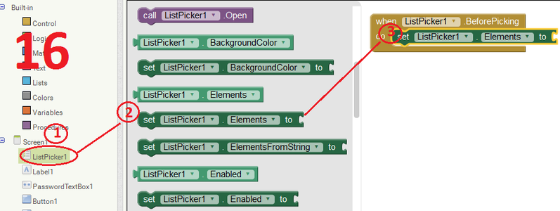
Let us, design blocks for List Picker. List Picker is a UI element when clicked it shows a list of corresponding elements here is the paired Bluetooth device. We have to add two blocks ListPicker.BeforePicking and ListPicker.AfterPicking (image 14). Complete Blocks are shown in figure 18 & 19.
Make apk file
Our design is complete, now we need to build the apk file for our android phone. Click to build menu and select "App(save .apk to my computer)". Wait for a minute. An apk file will download to your default download folder. Install and use it.
Step 8: A More Feature Rich Android App


In previous step I have showed you how to develop a basic bluetooth app in App Inventor. But that app is not so user friendly. It will not show you any message either your door is open or closed or bluetooth can not connected for any error. I have attached here a more advanced app for our project.
When you run you app this app check either your bluetooth radio is enable or not, if not enable a bluetooth enabling dialog will appear. Click yes to turn on your bluetooth radio. Then pair the device using pair device button. Then click to connect button, if successfully connected to any device the application shows the connected device's MAC address and name. Enter password to the password box then click the open door button, if you entered correct password door will be open and application will show you a message that your door is now open. Then enter password again if you want to close the door. If you give the wrong password, then app will show wrong password message.
Complete App Inventor source file (BTcontrol.aia) is attached herewith. If you did not like to make your own app or modify it, just download the BTcontrol.apk and install it to your android pone.
You can also download it from Google Play Store using the link:
https://play.google.com/store/apps/details?id=appinventor.ai_khairul_uapstu.BTcontrol&hl=en
For modifying the source click the "Projects" menu and select "Import project (.aia) from my computer" shown in figure 24 and browse the BTcontrol.aia file from your computer. After importing you can modify it easily.
If you want to know more about android app developing using App Inventor browse: http://appinventor.mit.edu/explore/ai2/tutorials.html. You can also try http://meta-guide.com/videography/100-best-appinventor-videos/
Attachments

Runner Up in the
Safety Challenge

Participated in the
Phone Contest

Participated in the
First Time Author Contest


