

Introduction: Arduino Power Supply 0 - 5V
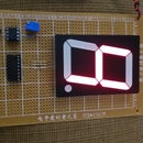


This project lets you manipulate the input of voltage from an Arduino microcontroller so that you enjoy of a power supply from 0 - 5 Volts. For getting the code, go to: http://pastebin.com/CDy28N55
What you will need:
Soldering iron
Solder
Wire #22, 1.5m
Driller
Drill bit of 3/8"
Nose pliers
Cutter of wires
Step 1: Schematic Diagram

In this step, you will observe the instructions for developing the project successfully. That is, observe carefully the schematic so that you can develop with success this project.
Step 2: List of Materials


In this step, you will see the following list of materials for the project.
1 Arduino Uno R3 DIP Edition (Revision 3)
1 Arduino MEGA Protoboard PCB (Rev3)
1 ABS Plastic Enclosure for Arduino Board - Fits UNO or MEGA
1 16x2 Character LCD Display - White on Blue 5V
2 Single Turn 3/8" Square Cermet 10k Potentiometer
1 9V Battery Snap with 2.1mm Barrel Plug
1 Cable USB2.0 A/B 3 Feet Black USB-A Male To USB-B Male
1 Alligator Clip-to-BNC Cable
1 Straight BNC Female Connector Panel Mount
1 Connector Unshrouded Header 40 Position 2.54mm Straight Thru-Hole
Step 3: Cutting the Arduino Enclosure Posts


In this step, you are going to prepare the plastic posts of your Arduino enclosure so that you can adjust perfectly the Arduino hardware into it. That is, cut the plastic posts of your Arduino enclosure according to the photo
Step 4: Drilling the Arduino Enclosure


In this step, you should drill a hole of 3/8" in your Arduino enclosure so that you later install the BNC connector. That is, using a drill bit of 3/8", do a hole of 3/8" in your Arduino enclosure.
Step 5: Preparing the BNC Connector


In this step, you should identify the positive and negative leads of your power supply, and it's through the BNC connector. That is, connect one wire to the gold pin of your BNC connector and another one to the silver clip terminal of that same connector so that the wires become positive(A0) and negative(GND) terminal respectively.
Step 6: Installing the BNC Connector


In this step, you are going to install the BNC connector in the hole done in the Arduino enclosure in step #5. That is, Install the BNC connector in the hole previously done in the Arduino enclosure in the step #5.
Step 7: Installing the Arduino


In this step, you are going to install perfectly the Arduino hardware into the Arduino enclosure. That is, once you prepared previously the Arduino enclosure, you are already ready to install the Arduino hardware.
Step 8: Installing the 16 Pins to Your LCD 16X2


In this step, you are going to cut one 16-pin of the Connector Unshrouded Header 40 Position 2.54mm Straight Thru-Hole so that you can install it into the holes of your LCD 16x2. That is, cut one 16-pin of the Connector Unshrouded Header 40 Position 2.54mm Straight Thru-Hole to install in your LCD 16x2.
Step 9: Visualizing Where Doing the Connections


In this step, you are going to visualize each connection between the PCB and the LCD 16x2 by inserting the LCD pins into the PCB temporarily according to the photo so that you know exactly what you are going to connect and from where.. That is, insert the LCD pins into the PCB temporarily so that you can visualize where you are going to do each connection between the LCD and the PCB.
Step 10: Preparing the Connections to Your LCD 16X2


Take away the LCD 16x2 from the PCB and begin doing the connections in the PCB considering the photo attached in this step to avoid errors. That is, doing the connections that you can see in the photo attached, you can continue without problem to the next step.
Step 11: Preparing the Connections to Both Pot of 10K


In this step, you are going to do the connections in the PCB to prepare the place of the installation of both potentiometers of 10K later.. That is, let circuit be ready to receive both potentiometers of 10K, doing the connections according to photo attached.
Step 12: Installing Both Pots of 10K


In this step, you are going to install both pots of 10K the contrast pot and the voltage regulator in the PCB and using the place prepared for it. That is, install the potentiometers in the PCB using the place prepared for it.
Step 13: Installing the LCD 16X2


In this step, you are going to install perfectly the LCD 16X2 on your PCB. That is, note that you already prepared previously the place where you are going to install the LCD 16X2.
Step 14: Installing the Connecting Pins on Arduino Mega PCB


In this step, you are going to install a few pins like interface between the Arduino hardware and the circuit that you are constructing. That is, prepare 4 pieces of pins from your 40-pin header straight male, cutting one piece of 8 pins, two piece of 6 pins, and one piece of 3 pins. Those pins should be installed as they are seen in the photo attached.
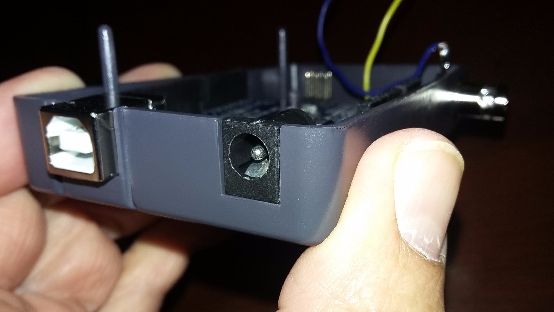
Step 15: Connecting the BNC Connector to Arduino Mega PCB


In this step, you are going to take the circuit completed in the step #14 and the part completed in the step #7 so that you can join them connecting the wires drawn from the BNC connector to A0 and GND. That is, connect the yellow wire to A0 and the blue one to GND
Step 16: A Look of the Whole Project Completed


In this step, you are going to mount the circuit completed on the Arduino hardware previously installed into the Arduino enclosure. That is, insert the circuit completed in the step #15 to mount it on the Arduino hardware installed before into the Arduino enclosure.
Step 17: Upload the Arduino Code at Pastebin Website


In this step, you can upload the code at: http://pastebin.com/CDy28N55
Once uploaded the code, you can connect the battery clip and battery and using also your Alligator Clip-to-BNC Cable,


