

Introduction: Arduino Robotic Arm
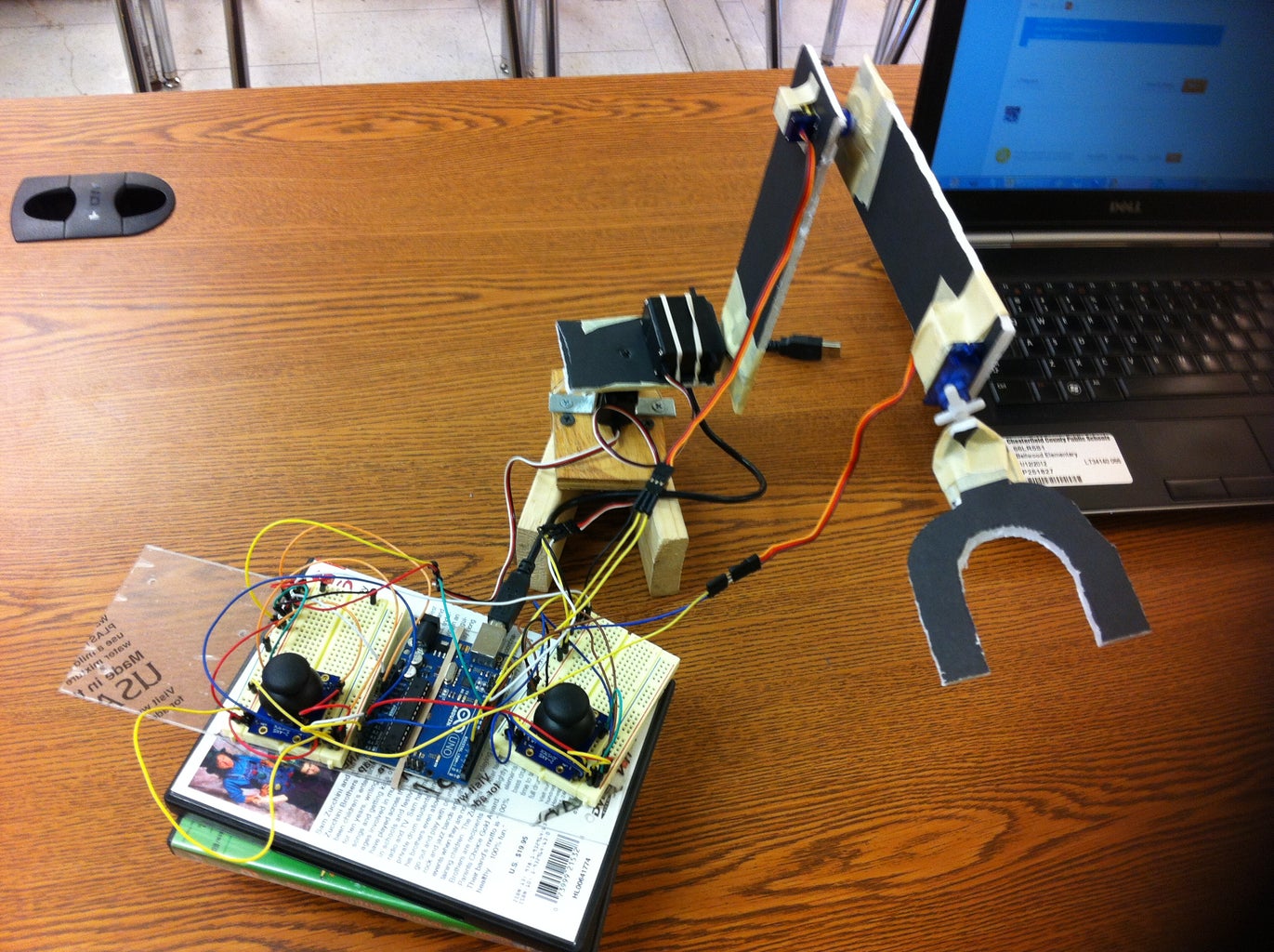


I will guide you step by step using simple construction parts. Remember this tutorial is to help you out and for you to have an idea on how to make your own robotic arm, using this one as an example. And like my other Arduinos Instructurables all the electronic parts were bought @ RADIOSHACK, except for the micro servos. They were bought @ Ebay.
NOTE: The construction of this robotic arm is for examples purposes only. I have use simple and cheap materials for this project.
And this tutorial is to help out other Arduino users on their personal projects. No criticism will be taken personal nor because the construction and materials used for the robotic arm. In other words use this tutorial to built you own and better robotic arm. Thank to all of you...BI()ME(H75
Enjoy;)
Step 1: Materials & Software

Here is the list in no particular order of the parts, tools and software needed for this project.
Parts:
1. Arduino UNO REV3
2. (2) Bread Boards
3. (2) Parallax servos
4. (2) Ebay micro servos
5. (2) Parllax analog joysticks
6. Breadboard jumper cables
7. Masking Tape
8. Foam board
9. Utility knife, scissors.
10. PATIENCE (a lot)
Software:
Arduino software 0023
NOTE: I rather use this version because the newer one gives me a lot of headaches and issues.
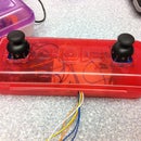
Step 2: Cutting & Assembling Part 1


There is not much to explain in this step. Just cut the foam board any way you want mine is: 6.5 X 1.5 inches and the other one is 4.5 X 1.5 inches. all you have to to is to cut and make holes to fit the servos. Remember the main purpose of this tutorial is to move the servos with the joysticks.
NOTE: Before cutting and putting everything together you need to test the movement of the servos and arrange them in the right place, for the robotic arm and its movements. (after steps 5-8 are complete)
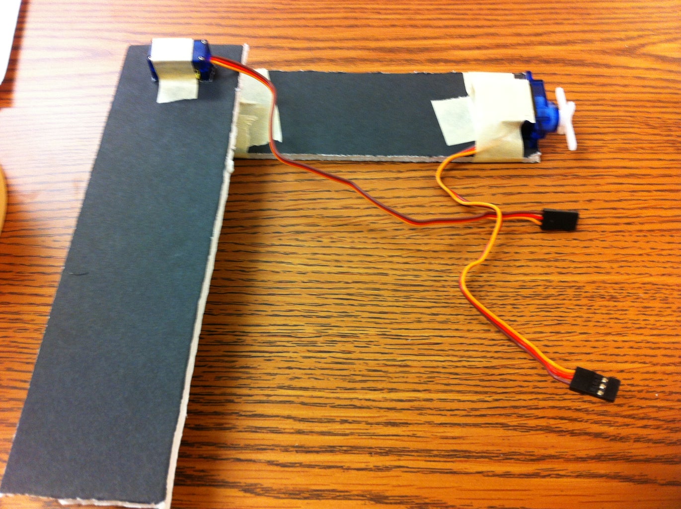
Step 3: Cutting & Assembling Part 2


I have use school tape to hold everything in position. The base is made with recycle pieces of wood that I have found around the garage. Notice how the front servo for the claw rotation it is placed.
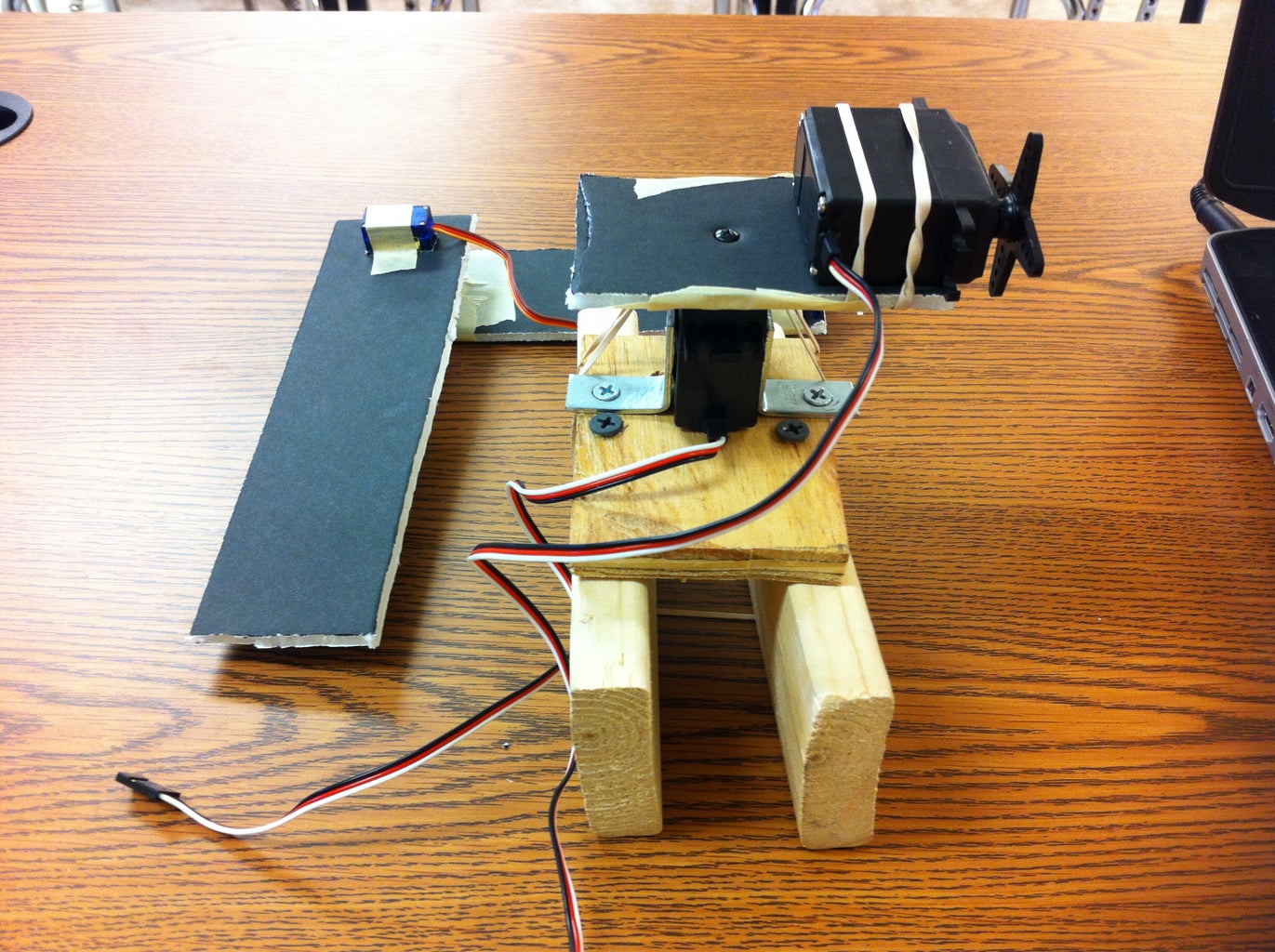
Step 4: Cutting & Assembling Part 3
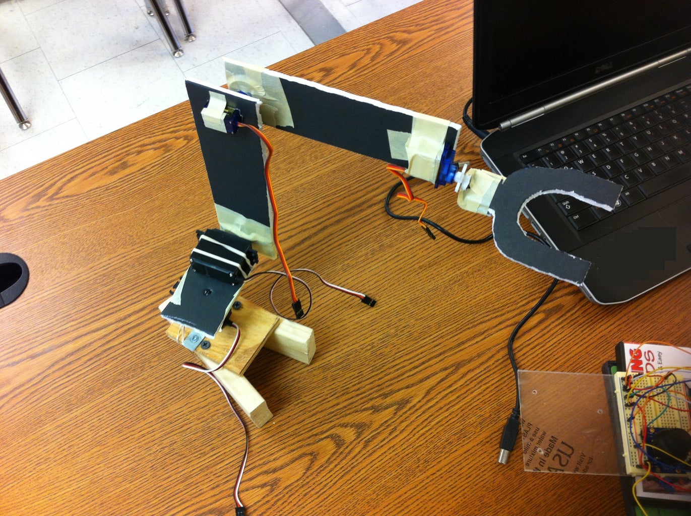
Not much to explain in here, just putting everything together. And I will refer to each connection and servos with a number for your understanding.
EX: Servo 1 base ( body rotation)
Servo 2 arm_1 ( up/down)
Servo 3 arm_2 ( up/down)
Servo 4 claw ( claw rotation)
NOTE: The connections are WAYYY confusing and NOT clear but I will explain them in the next steps.
Step 5: Servos Connections 1 & 2

In here I will show how the connections for the servos 1 and 2.
SERVO 1 is the standard servo for the rotation of the base.
SERVO 2 is another standard servo for the up and down movements of what I refer as ARM_1 .
Servo 1 connections: Red wire: Arduino 5V
Black wire: Arduino GND
Yellow wire: Arduino Digital PWM 10
Servo 2 connections: Red wire: Arduino 5V
Black wire: Arduino GND
Yellow wire: Arduino Digital PWM 11
Step 6: Servos Connections 3 & 4

In here I will show how the connections for the servos 3 and 4.
SERVO 3 is a micro servo for the up and down movements of what I refer as ARM_2 .
SERVO 4 is a another micro servo for the rotation of the claw.
Servo 3 connections: Red wire: Arduino 5V
Black wire: Arduino GND
Yellow wire: Arduino Digital PWM 3
Servo 4 connections: Red wire: Arduino 5V
Black wire: Arduino GND
Yellow wire: Arduino Digital PWM 4
Step 7: Joystick Connections (Joy_1) LEFT

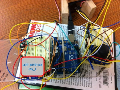
Here is the connections for Joy_1 or the LEFT joystick. The Parallax joystick has 2 grounds and they need to be connected. For all this connections you need 2 bread boards for each joystick. (or a big one) But I feel less confusing when I use for each joystick a small bread board. Pay attention to all the connections and double check them.
L/R+ and U/R+ is the 5V Arduino connection (power)
GND and GND is for ground on the arduino
L/R and L/R goes to the Arduino ANALOG connection A2
U/D and U/D goes to the Arduino ANALOG connection A5
Step 8: Joystick Connections (Joy_2)
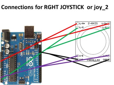

Here is the connections for Joy_2 or the RGHT joystick. The Parallax joystick has 2 grounds and they need to be connected. For all this connections you need 2 bread boards for each joystick. (or a big one) But I feel less confusing when I use for each joystick a small bread board. Pay attention to all the connections and double check them.
L/R+ and U/R+ is the 5V Arduino connection (power)
GND and GND is for ground on the arduino
L/R and L/R goes to the Arduino ANALOG connection A4
U/D and U/D goes to the Arduino ANALOG connection A3
Step 9: Testing the Servos


Time to test the servos and all the connections. DOUBLE CHECK all the connections.
It is a good practice to use 2 AA batteries pack as the power source, in at least in one of the bread boards.
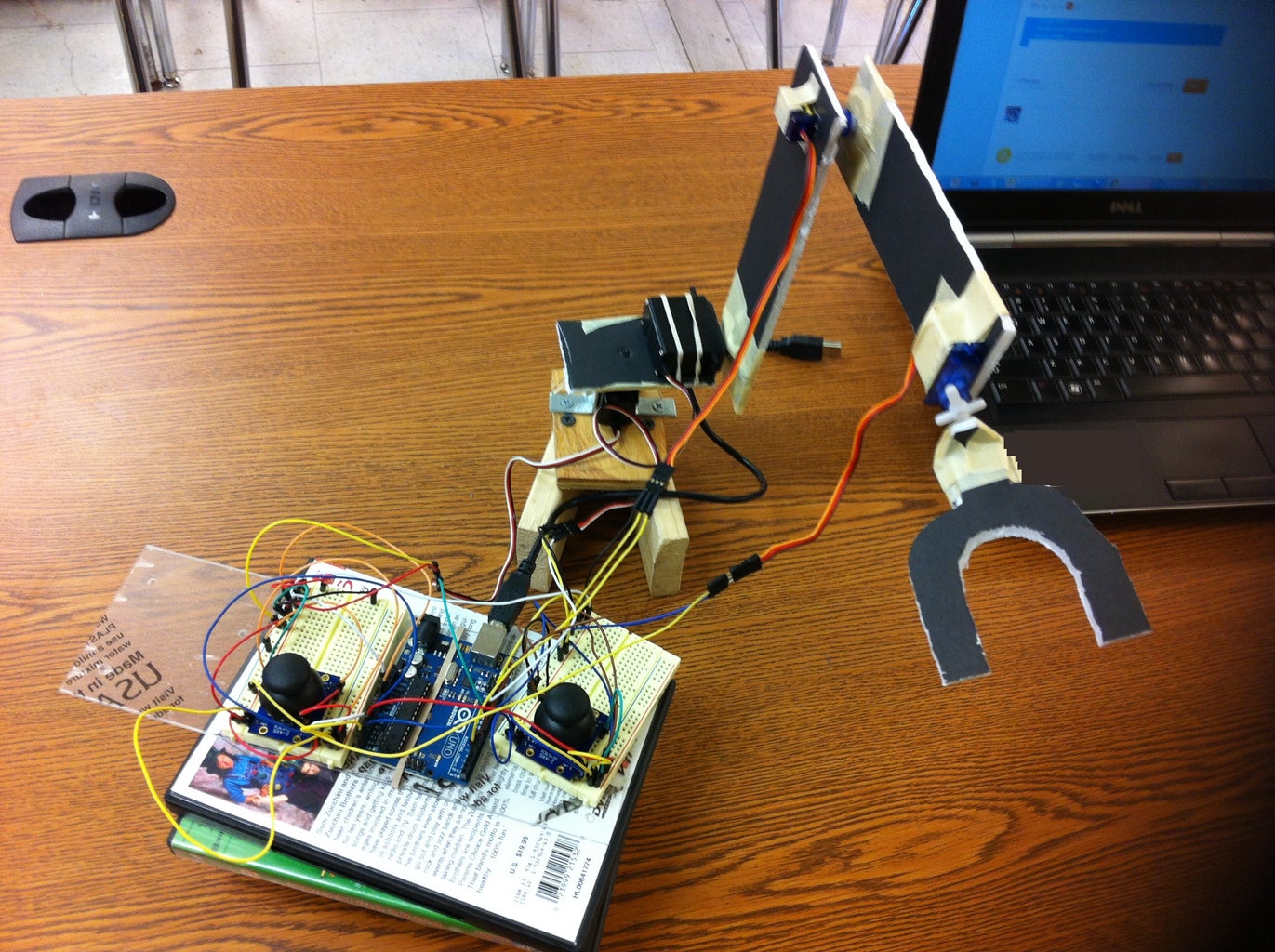
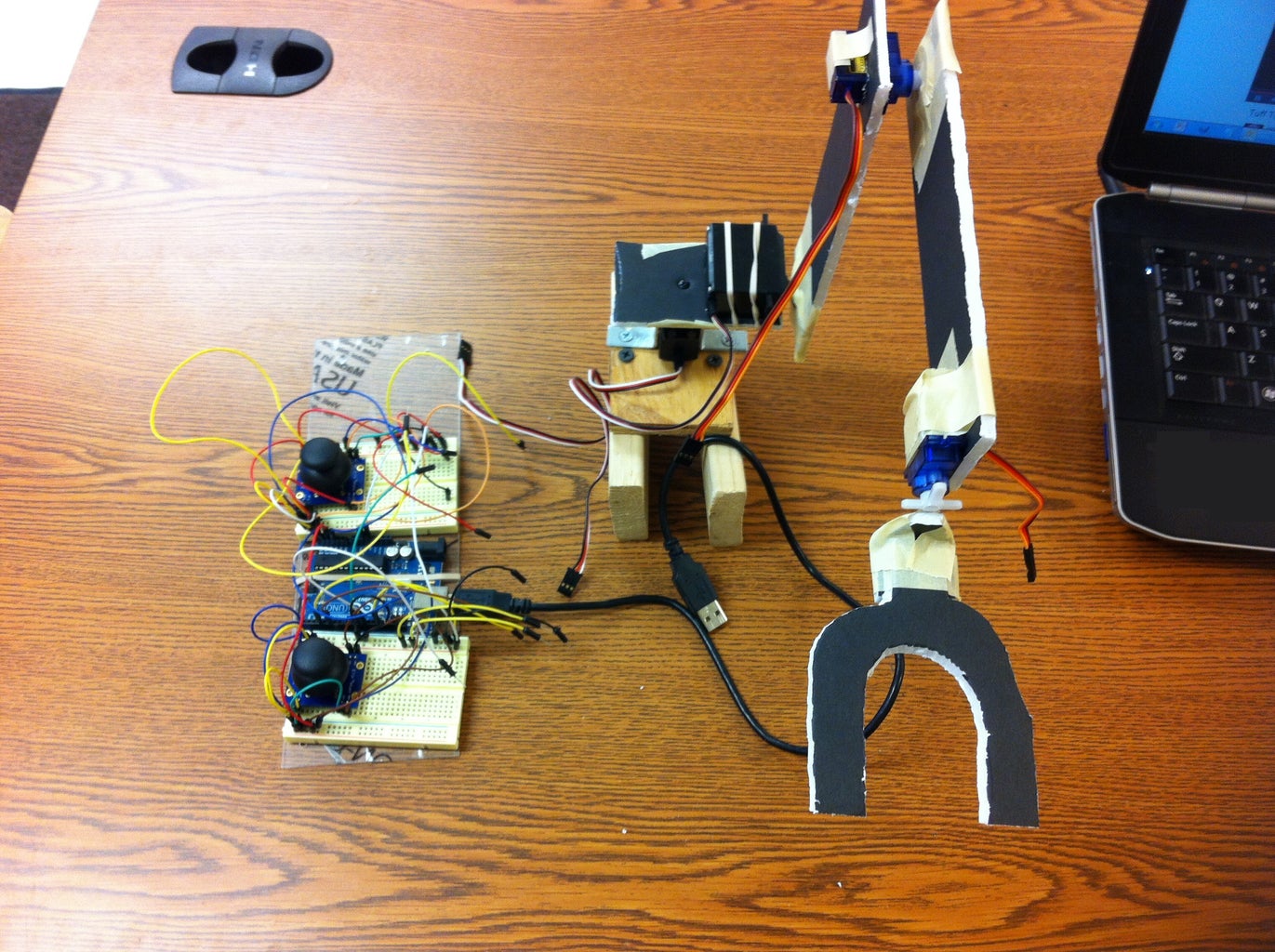
Step 10: Finish Product

Do another test with all the servos in place. DOUBLE CHECK connections.
Step 11: The CODE
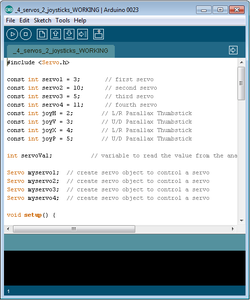
THE CODE: (ALWAYS TEST THE CODE BEFORE UPLOADING TO THE ARDUINO)
#include <Servo.h>
const int servo1 = 3; // first servo
const int servo2 = 10; // second servo
const int servo3 = 5; // third servo
const int servo4 = 11; // fourth servo
const int joyH = 2; // L/R Parallax Thumbstick
const int joyV = 3; // U/D Parallax Thumbstick
const int joyX = 4; // L/R Parallax Thumbstick
const int joyP = 5; // U/D Parallax Thumbstick
int servoVal; // variable to read the value from the analog pin
Servo myservo1; // create servo object to control a servo
Servo myservo2; // create servo object to control a servo
Servo myservo3; // create servo object to control a servo
Servo myservo4; // create servo object to control a servo
void setup() {
// Servo
myservo1.attach(servo1); // attaches the servo
myservo2.attach(servo2); // attaches the servo
myservo3.attach(servo3); // attaches the servo
myservo4.attach(servo4); // attaches the servo
// Inizialize Serial
Serial.begin(9600);
}
void loop(){
// Display Joystick values using the serial monitor
outputJoystick();
// Read the horizontal joystick value (value between 0 and 1023)
servoVal = analogRead(joyH);
servoVal = map(servoVal, 0, 1023, 0, 180); // scale it to use it with the servo (result between 0 and 180)
myservo2.write(servoVal); // sets the servo position according to the scaled value
// Read the horizontal joystick value (value between 0 and 1023)
servoVal = analogRead(joyV);
servoVal = map(servoVal, 0, 1023, 70, 180); // scale it to use it with the servo (result between 70 and 180)
myservo1.write(servoVal); // sets the servo position according to the scaled value
delay(15); // waits for the servo to get there
// Read the horizontal joystick value (value between 0 and 1023)
servoVal = analogRead(joyP);
servoVal = map(servoVal, 0, 1023, 70, 180); // scale it to use it with the servo (result between 70 and 180)
myservo4.write(servoVal); // sets the servo position according to the scaled value
delay(15); // waits for the servo to get there
// Read the horizontal joystick value (value between 0 and 1023)
servoVal = analogRead(joyX);
servoVal = map(servoVal, 0, 1023, 70, 180); // scale it to use it with the servo (result between 70 and 180)
myservo3.write(servoVal); // sets the servo position according to the scaled value
delay(15); // waits for the servo to get there
}
/**
* Display joystick values
*/
void outputJoystick(){
Serial.print(analogRead(joyH));
Serial.print ("---");
Serial.print(analogRead(joyV));
Serial.println ("----------------");
Serial.print(analogRead(joyP));
Serial.println ("----------------");
Serial.print(analogRead(joyX));
Serial.println ("----------------");
}
Step 12: NEW CODE!!!!

Here is the new code for this robotic arm I have add 1 more servo for the opening and closing the CLAW with a potentiometer! It will help in case you want to manage the pressure on the claw ENJOY!!!! ;
CODE:
#include <Servo.h>
const int servo1 = 3; // first servo
const int servo2 = 10; // second servo
const int servo3 = 5; // third servo
const int servo4 = 11; // fourth servo
const int servo5 = 9; // fifth servo
const int joyH = 2; // L/R Parallax Thumbstick
const int joyV = 3; // U/D Parallax Thumbstick
const int joyX = 4; // L/R Parallax Thumbstick
const int joyP = 5; // U/D Parallax Thumbstick
const int potpin = 0; // O/C potentiometer
int servoVal; // variable to read the value from the analog pin
Servo myservo1; // create servo object to control a servo
Servo myservo2; // create servo object to control a servo
Servo myservo3; // create servo object to control a servo
Servo myservo4; // create servo object to control a servo
Servo myservo5; // create servo object to control a servo
void setup() {
// Servo
myservo1.attach(servo1); // attaches the servo
myservo2.attach(servo2); // attaches the servo
myservo3.attach(servo3); // attaches the servo
myservo4.attach(servo4); // attaches the servo
myservo5.attach(servo5); // attaches the servo
// Inizialize Serial
Serial.begin(9600);
}
void loop(){
servoVal = analogRead(potpin);
servoVal = map(servoVal, 0, 1023, 0, 179);
myservo5.write(servoVal);
delay(15);
// Display Joystick values using the serial monitor
outputJoystick();
// Read the horizontal joystick value (value between 0 and 1023)
servoVal = analogRead(joyH);
servoVal = map(servoVal, 0, 1023, 0, 180); // scale it to use it with the servo (result between 0 and 180)
myservo2.write(servoVal); // sets the servo position according to the scaled value
// Read the horizontal joystick value (value between 0 and 1023)
servoVal = analogRead(joyV);
servoVal = map(servoVal, 0, 1023, 70, 180); // scale it to use it with the servo (result between 70 and 180)
myservo1.write(servoVal); // sets the servo position according to the scaled value
delay(15); // waits for the servo to get there
// Read the horizontal joystick value (value between 0 and 1023)
servoVal = analogRead(joyP);
servoVal = map(servoVal, 0, 1023, 70, 180); // scale it to use it with the servo (result between 70 and 180)
myservo4.write(servoVal); // sets the servo position according to the scaled value
delay(15); // waits for the servo to get there
// Read the horizontal joystick value (value between 0 and 1023)
servoVal = analogRead(joyX);
servoVal = map(servoVal, 0, 1023, 70, 180); // scale it to use it with the servo (result between 70 and 180)
myservo3.write(servoVal); // sets the servo position according to the scaled value
delay(15); // waits for the servo to get there
}
/**
* Display joystick values
*/
void outputJoystick(){
Serial.print(analogRead(joyH));
Serial.print ("---");
Serial.print(analogRead(joyV));
Serial.println ("----------------");
Serial.print(analogRead(joyP));
Serial.println ("----------------");
Serial.print(analogRead(joyX));
Serial.println ("----------------");
}
Step 13: Troubleshooting

1. The servos won't move.
A. Check the connections, remember in this tutorial we use PWM pins for the servos and the Analog pins for the joysticks.
2. When I upload the code to the board the servos, they start vibrating.
A. It means that either U/D+ or L/R+ are not properly connected. Double check your connections. You have to disconnect the usb from the board to verify connections try to review the connections on the steps 5 -8.
3. I double check the connections and the servos wont move.
A. Take out the joystick and reconnect it again in the bread board by pressing it down to make sure it is connected. Connections have to be tight from the joystick to the bread board.
4. There is a vibration from one of the servos.
This happens because of the combination of micro servos and standard servos. (I did this project with 4 Parallax standard servos with no vibration issues at all). The micro servos used in here are the cheap ones from Ebay. They are good for testing purposes though.
Any other help or issues you have feel free to let me know and I will be glad to help all of you. ;)

Participated in the
Hardware Hacking

Participated in the
Manly Crafts Contest


